Wavelength and filter arrangement for WDM networks

a filter arrangement and wavelength management technology, applied in the field of fiber optic communication, can solve problems such as inability to be usefully retrieved, and achieve the effect of efficient wavelength management and filtering

Inactive Publication Date: 2005-08-18
CIENA
View PDF4 Cites 2 Cited by
  • Summary
  • Abstract
  • Description
  • Claims
  • Application Information

AI Technical Summary

Benefits of technology

[0010] Yet another aspect of the invention can be implemented in the context of demultiplexing three wavelength channels separated by a particular frequency within a band. Typically, three band-pass filters, each being sufficiently narrow so as to eliminate crosstalk between the wavelength channels would be used. However, if the center wavelength channel is first removed using a narrow band-pass filter, the remaining two wavelength channels can be separated using two wider (i.e., less expensive) filters.

Problems solved by technology

However, since filters do not have infinitely sharp cutoffs, a range of wavelengths near the cutoff (the boundary region) of a dichroic filter are partially transmitted and partially reflected, and therefore cannot be usefully retrieved.

Method used


Image

  • Wavelength and filter arrangement for WDM networks
  • Wavelength and filter arrangement for WDM networks
  • Wavelength and filter arrangement for WDM networks

Examples


Embodiment Construction

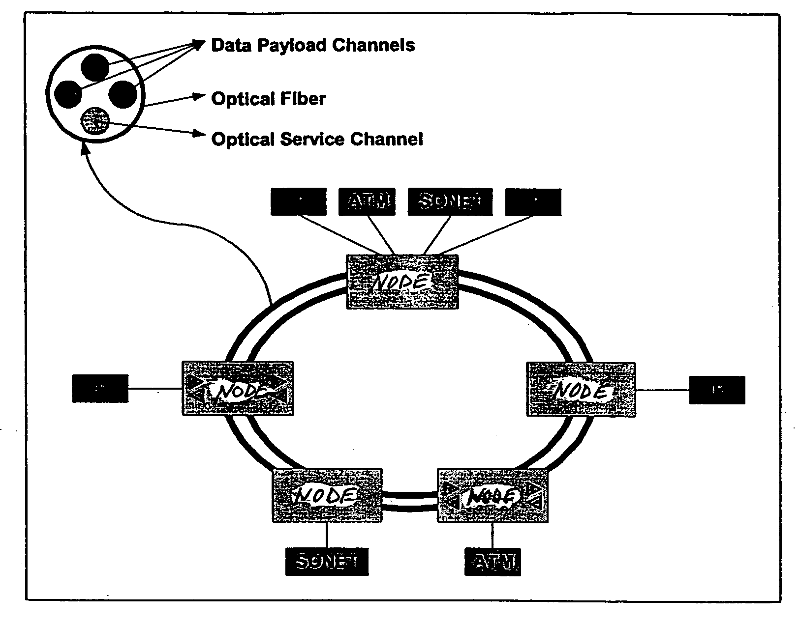
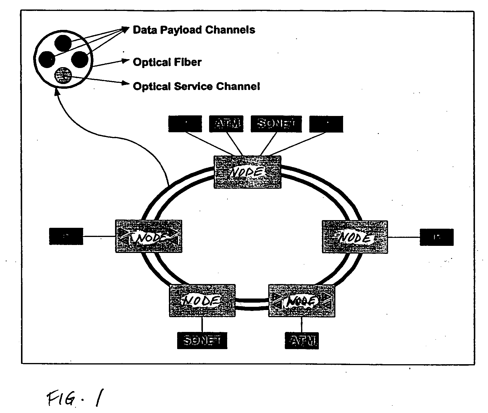
[0021] Referring to FIG. 1, there is shown a two-fiber optical bi-directional line switched ring (O-BLSR) 10. Ring 10 includes a plurality of nodes 20 which are interconnected by fibers 25. Each node can send and receive signals to and from adjacent nodes on ring 10. The nodes are designated 20a, 20b, 20c etc. In addition, terminal equipment, such as IP, ATM and SONET equipment, can be connected to a node to send and receive traffic from ring 10.

[0022] Each pair of adjacent nodes is connected by two fibers. Each fiber 25 carries a number of wavelength channels, including a number of data payload channels and an optical service channel (OSC). The data payload channels are bit-rate and protocol independent thus allowing the transport of various types of traffic such as IP, ATM and / or SONET traffic. The OSC is used for node-to-node communication to facilitate various network operations ranging from protection switching to customized configuration.

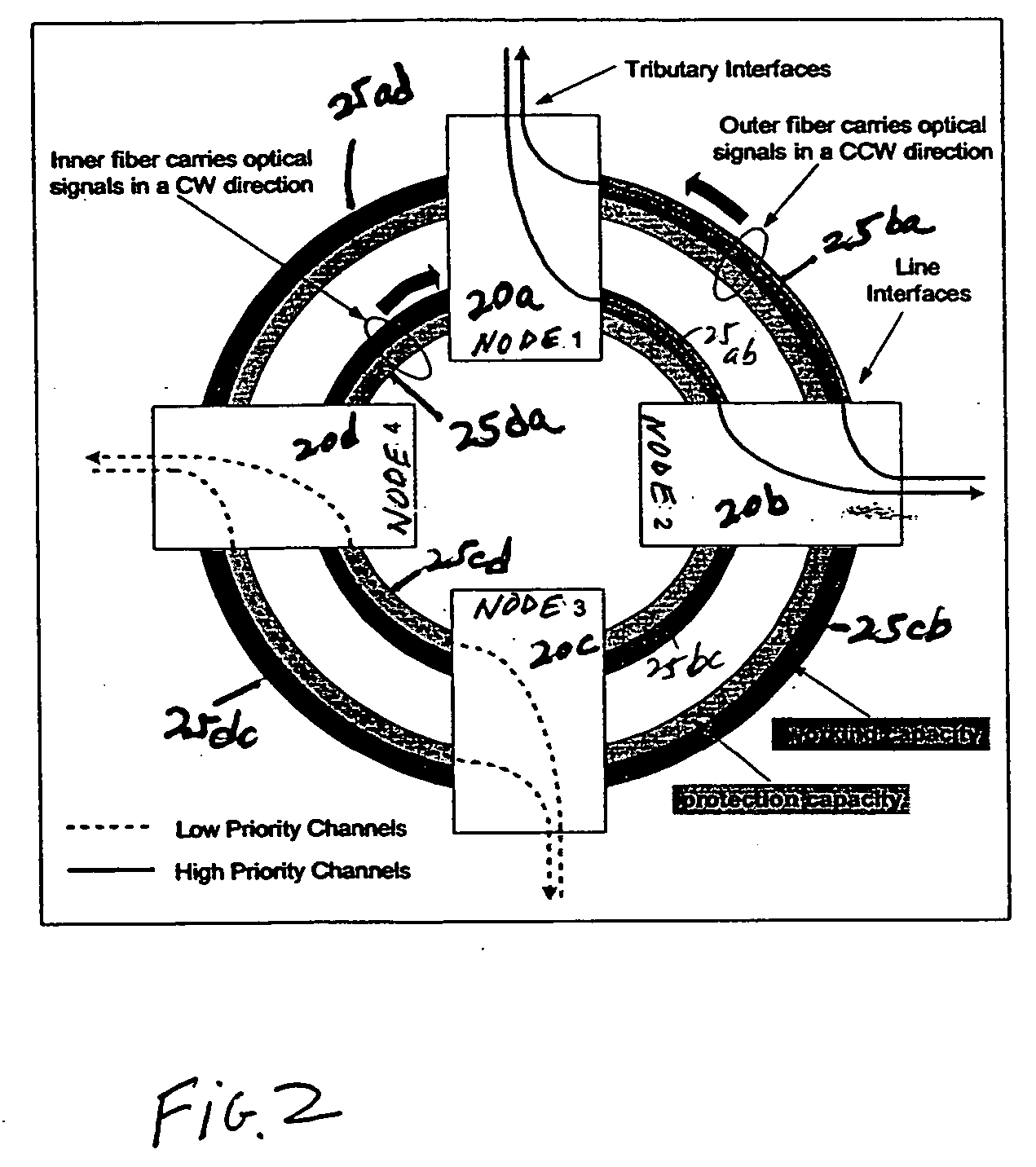
[0023] The nomenclature regarding fib...


PUM

PropertyMeasurementUnit
wavelengthaaaaaaaaaa
wavelength bandsaaaaaaaaaa
wavelength bandaaaaaaaaaa

Abstract

In a ring having first and second adjacent nodes, and two fibers carrying information between the first and second nodes, the first fiber carries information in one direction, while the second fiber carries information in another direction. Each fiber includes wavelength capacity allocated to working and protection traffic. The working and protection wavelength capacities in the first fiber are respectively assigned to first and second disjoint sets of wavelengths, while the working and protection wavelength capacities in the second fiber are respectively assigned to the second and first disjoint sets of wavelengths.

Description

CROSS-REFERENCE TO RELATED APPLICATION [0001] The present application claims the benefit of priority under 35 U.S.C. § 119 from the provisional patent application, U.S. Patent Application Ser. No. 60 / 210,231, filed on Jun. 6, 2000, the disclosure of which, including all attached documents, is hereby incorporated by reference as if set forth in full in this document for all purposes.BACKGROUND OF THE INVENTION [0002] The present invention relates generally to fiber optic communications, and more specifically to techniques used in connection with wavelength assignment, wavelength filtering, and protection switching in wavelength division multiplexing (WDM) networks. [0003] Photonic transmission, amplification, and switching techniques provide flexible means of provisioning, configuring, and managing modern high capacity telecommunication networks. The physical layer in the network, which includes the transmission equipment and the fiber layer used for signal transport, needs to be rec...

Claims


Application Information

Patent Timeline
Patent Type & Authority Applications(United States)
IPC IPC(8): H04B10/213H04J3/08H04J14/02
CPCH04J3/085H04J14/0227H04J14/0241H04J14/0295H04J14/0283
Inventor CHIN, HON WAHSHARMA, ROHITJESSUP, HOLDENZACCARIN, DENIS
Owner CIENA
Why Eureka
Try Eureka