
Wire wound tooling

a tooling and wire technology, applied in the field of wire wound tooling, can solve the problems of destroying the entire mold, increasing the cost, and achieving the difficulty of obtaining the wire with some difficulty and increasing the cost, so as to improve the uniformity of products, improve the thermal control of mold cavities, and reduce the effect of wire thermal mass

Inactive Publication Date: 2005-08-18
3M INNOVATIVE PROPERTIES CO
View PDF38 Cites 2 Cited by
  • Summary
  • Abstract
  • Description
  • Claims
  • Application Information

AI Technical Summary

Benefits of technology

This approach enables the formation of articles with high aspect ratio protrusions and increased mold cavity density, offering improved precision, cost-effectiveness, and the ability to maintain uniformity and structural integrity, while allowing for easier maintenance and replacement of damaged components.

Problems solved by technology

As a result, the cavities are cylindrical in shape and, although some precision can be obtained in depth, diameter and spacing between cavities, it is obtained with some difficulty and increased costs.
Furthermore, damage to the mold surface typically requires that the entire mold be discarded.
Furthermore, precise control over the depth of the cavities is difficult to obtain due to variability in the material used to construct the mold, the power of the laser beam, the energy distribution within the beam, beam focus, etc.
Disadvantages of these designs include the cost of manufacturing the mold disks with adequate precision to ensure that the mold cavities are of the same depth, length, spacing, etc.
Size limitations imposed on the disks by manufacturing difficulties can, in turn, limit line speed in processes using the tools.
Other disadvantages of this design include non-uniform cooling of the mold cavities, non-uniformities in the products produced by the stacked plates, etc.

Method used


Image

  • Wire wound tooling
  • Wire wound tooling
  • Wire wound tooling

Examples


Embodiment Construction

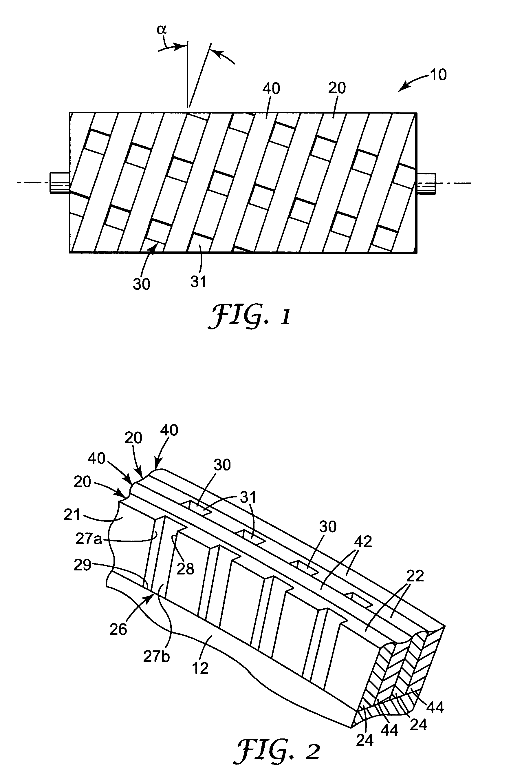
[0059] The present invention provides tool rolls and methods of using the tool rolls to manufacture articles with one or more structured surfaces. The tool rolls include an outer surface that, when used in connection with materials of the proper viscosity or formability, can form a structured surface on an article. Because the tools are manufactured in roll-form, they can be advantageously used in continuous manufacturing processes to form e.g., films, sheets, etc. Alternatively, discrete articles may be processed using the tool rolls of the present invention.

[0060] The tool rolls of the present invention may include mold cavities in their outer surfaces that, when used in connection with materials of the proper viscosity or formability, can form protrusions or structures on at least one surface of a film. Alternatively, two such rolls can be used in combination to form a film in which both major surfaces exhibit protrusions or structures.

[0061]FIG. 1 depicts one illustrative embo...


PUM

PropertyMeasurementUnit
aspect ratioaaaaaaaaaa
heightaaaaaaaaaa
heightaaaaaaaaaa

Abstract

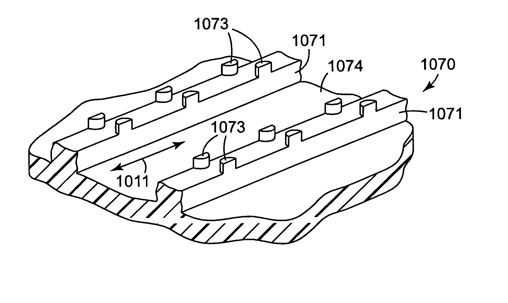
Tool rolls and methods of using the tool rolls to manufacture articles with one or more structured surfaces are disclosed. The tool rolls include an outer surface that, when used in connection with materials of the proper viscosity or formability, can form a structured surface on an article. Because the tools are manufactured in roll-form, they can be advantageously used in continuous manufacturing processes. Alternatively, discrete articles may be processed using the tool rolls. The tool rolls are constructed of a cylindrical base roll and are wrapped with one or more continuous wires in a helical pattern. The wires are used, in essence, to form a structured surface on the tool roll that is the negative of the structured surface to be formed on the articles processed using the tool roll. One of the wires wound around the base roll may include depressions formed therein that, when wound in helical coils about the base roll, form cavities on the outer surface of the tool roll. Alternatively, the helical pattern of one or more wound wires may be used to form a continuous helical structured surface, e.g., a helical groove or grooves.

Description

CROSS REFERENCE TO RELATED APPLICATIONS [0001] This application is a division of U.S. Patent Application Ser. No. 10 / 438,082, filed May 14, 2003, now allowed.FIELD OF THE INVENTION [0002] The present invention relates to the field of manufacturing articles with structured surfaces. More particularly, the present invention provides tooling for manufacturing articles with one or more structured surfaces, methods of manufacturing the tooling, and methods of using the tooling to manufacture articles with one or more structured surfaces. BACKGROUND [0003] Articles with one or more structured surfaces find a variety of uses. The articles may be provided as films that exhibit, e.g., increased surface area, structures used to provide a mechanical fastener, optical properties, etc. When these films are manufactured for use as mechanical fasteners, the protrusions that are found on the structured surface are commonly referred to as hooks. The hooks may be formed in a curved shape or they may ...

Claims


Application Information

Patent Timeline
Patent Type & Authority Applications(United States)
IPC IPC(8): A44B18/00B29C43/22B29C43/46B29C48/885B29C59/00B29C59/02B29C59/04B29C69/02
CPCA44B18/0049Y10T428/2457B29C43/222B29C43/46B29C47/003B29C47/0038B29C47/88B29C59/002B29C59/025B29C59/04B29C2043/465B29C2791/006B29L2005/00B29L2031/729B29C2043/461A44B18/0061B29C48/08B29C48/12B29C48/001B29C48/914B29C48/885B29C59/02B21B1/40A44B18/00
Inventor GORMAN, MICHAEL R.KAMPFER, ROBERT D.LALIBERTE, THOMAS R.
Owner 3M INNOVATIVE PROPERTIES CO
Learn More