Mobile communication system, mobile station, base station, communication path quality estimation method used for the same

a mobile communication system and communication path technology, applied in the field of communication path quality estimation method, can solve the problems of affecting the accuracy of the adaptive antenna, interference to the user receiving packets, and the difference between the estimated communication path quality upon reception, so as to achieve the effect of higher accuracy

Inactive Publication Date: 2005-08-18
NEC CORP
View PDF13 Cites 54 Cited by
  • Summary
  • Abstract
  • Description
  • Claims
  • Application Information

AI Technical Summary

Benefits of technology

[0033] That is, with respect to the system that uses the adaptive antenna in the base station and carries out the high speed downlink packet transmission, the mobile communication system of the present invention is characterized in that the mobile station performs the communication control by cooperatively using the communication path quality in the standby state and the communication path quality in the receiving state. With this arrangement, in the present invention, the estimation accuracy of the communication path quality at the start of communication is improved so that the communication control with higher accuracy is made possible.

Problems solved by technology

However, there arises a problem that since the common pilot channel is not transmitted to a particular mobile station with a directivity given thereto, the communication path differs from a channel that actually transmits packets so that there occurs a difference between the estimated communication path quality and a communication path quality upon reception.
However, if the control channels are allocated to all users in communication and on standby to carry out the communication path quality measurement, signal power to be allocated to the users on standby, which is not primarily necessary, increases and this causes interference to the users receiving packets.
Thus, there is no merit of applying the adaptive antenna.
Alternatively, if, as conventional, dedicated control channels controlled in directivity and given to only those users receiving packets are used for the communication path quality estimation, there is a problem that the communication path quality estimation cannot be carried out while waiting for packets.
Further, in the foregoing conventional mobile communication system, although MCS selection is carried out based on the communication path quality, when the adaptive antenna is used, the data channels of other mobile stations are separated in a standby state by the directivity of the adaptive antenna, and therefore, it is not possible to know degradation of the communication path quality due to multipath interference to the data channel in a communication state.
Consequently, in the conventional mobile communication system, there arises a problem that the communication path quality measured in the standby state becomes higher than the communication path quality in the communication state, and therefore, if MCS selection is carried out based on the communication path quality measured in the standby state, the probability of occurrence of packet reception errors becomes high so that the transmission efficiency is reduced.
The communication path quality becomes poorer with respect to such a mobile station that performs packet transmission at a higher time rate in the predetermined time.
Therefore, in the conventional method, there arises a problem that it is not possible to perform the comparison in the same condition.
Here, since the MCS level of the mobile station brought into the communication state is determined on the basis of the communication path quality in the standby state, the probability of occurrence of packet errors increases, which further brings about an increase in the number of times of retransmission.
Consequently, there arises a problem that the system throughput is reduced.

Method used


Image

  • Mobile communication system, mobile station, base station, communication path quality estimation method used for the same
  • Mobile communication system, mobile station, base station, communication path quality estimation method used for the same
  • Mobile communication system, mobile station, base station, communication path quality estimation method used for the same

Examples


first embodiment

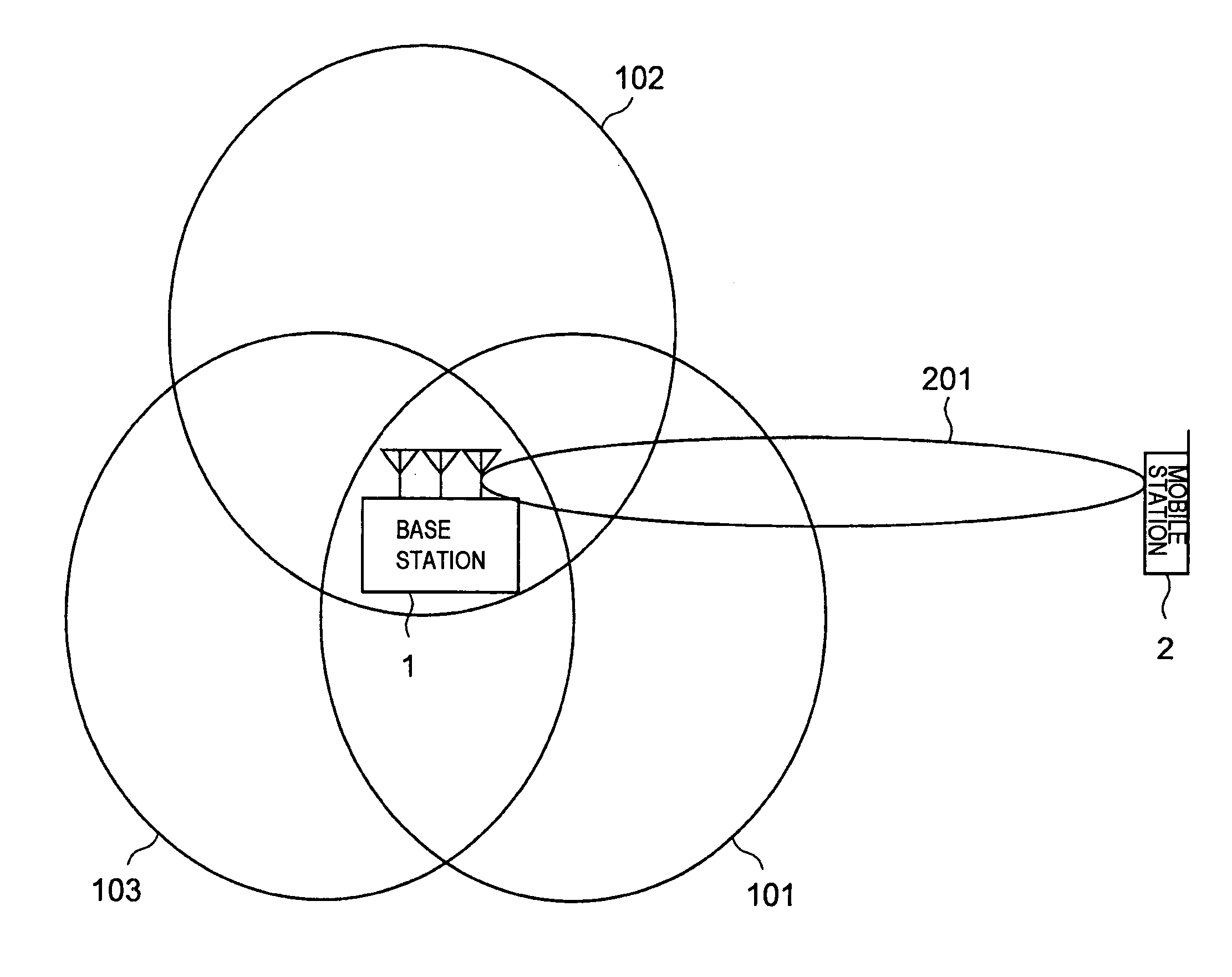
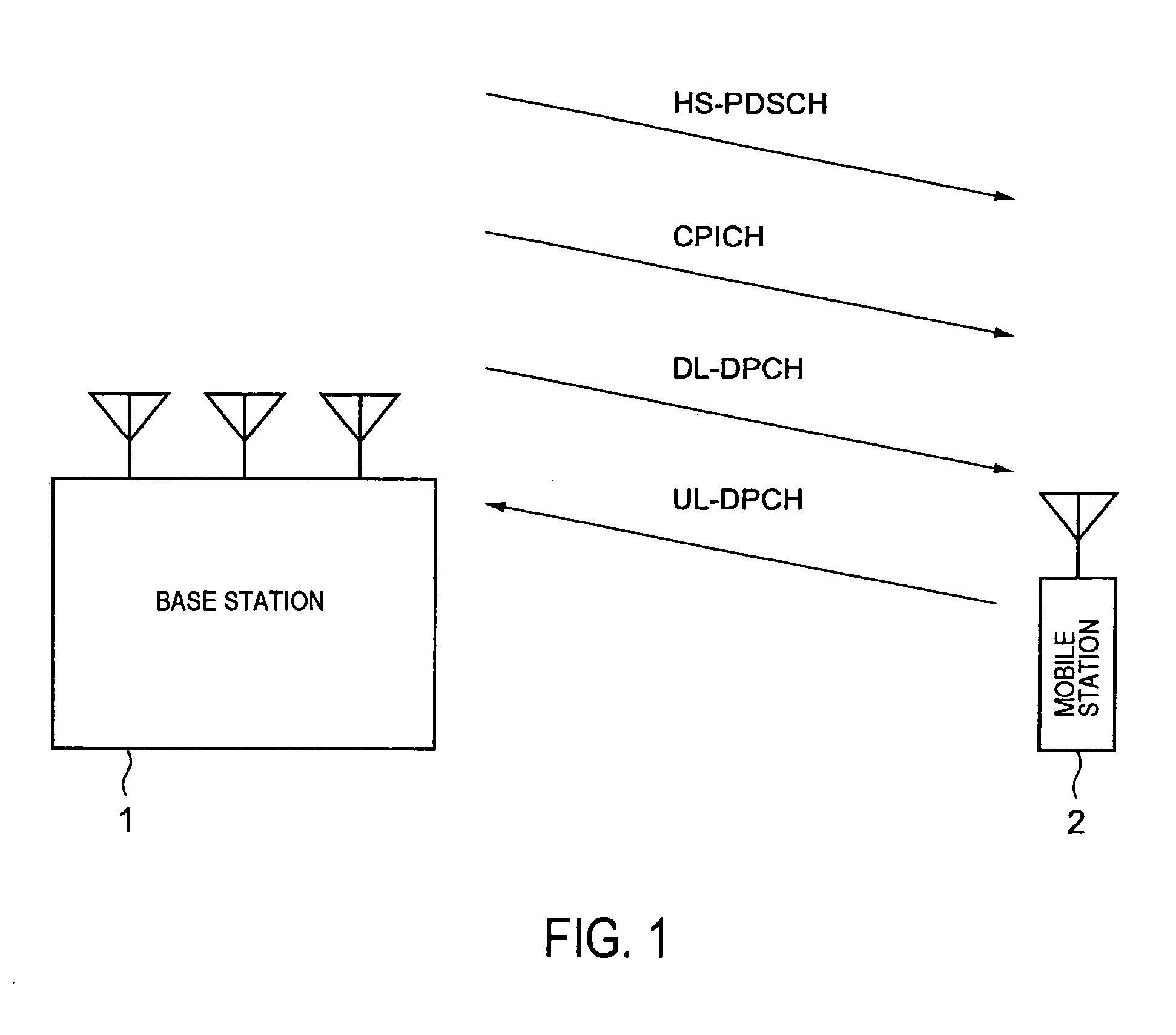
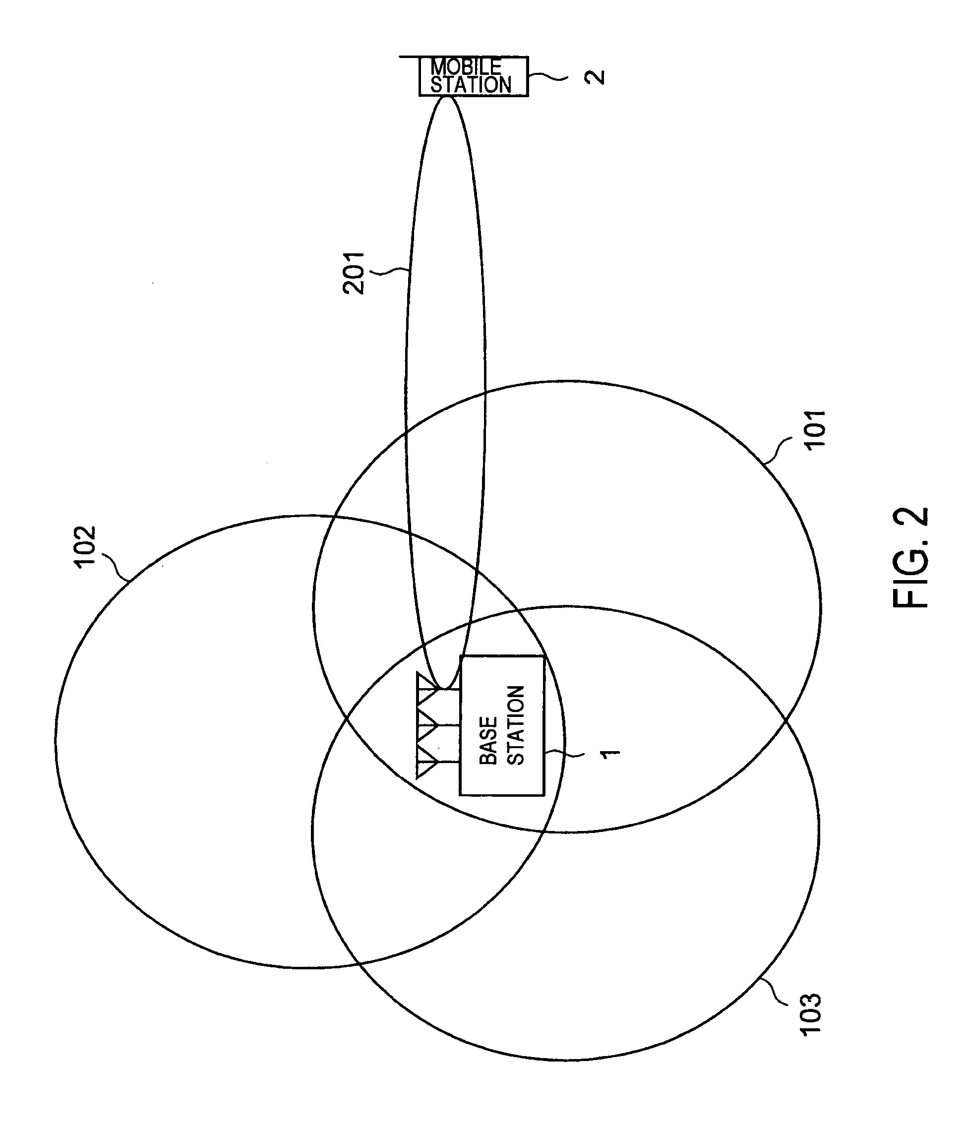
[0060]FIG. 2 is a block diagram showing a structure of the mobile communication system according to the present invention. As shown in FIG. 2, the base station 1 transmits different common pilot channels by respective beams 101 to 103 that are controlled in directivity by adaptive antennas. When the base station 1 transmits data to the mobile station 2, the base station 1 transmits the data channel (HS-PDSCH) and the downlink dedicated control channel (DL-DPCH) by the use of a beam 201 individually controlled in directivity. The mobile station 2 estimates a communication path quality by switching between the common pilot channel (CPICH) and the dedicated control channel.

[0061]FIG. 3 is a block diagram showing a structure of the mobile station 2 in FIG. 2. In FIG. 3, the mobile station 2 comprises an antenna 21, a transmission / reception duplex section (DUP: duplexer) 22, a receiving section (Rx) 23, a channel (CH) selecting section 24, a communication path estimating section 25, a us...

third embodiment

[0090] In FIG. 9, the base station according to the present invention comprises antennas 11 to 13, a transmission / reception duplex section (DUP) 14, a receiving section (Rx) 15, mobile station corresponding units 31-1 to 31-3, a scheduling control section 32, and a transmission section (Tx) 19.

[0091] Further, the mobile station corresponding units 31-1 to 31-3 comprise information separating sections 16-1 to 16-3 (information separating sections 16-2 and 16-3 are not illustrated), MCS level control sections 17-1 to 17-3 (MCS level control sections 17-2 and 17-3 are not illustrated), and signal combining sections 18-1 to 18-3 (signal combining sections 18-2 and 18-3 are not illustrated).

[0092] Signals received at the antennas 11 to 13 are inputted into the receiving section 15 serving for respective mobile stations via the transmission / reception duplex section 14 and demodulated in the receiving section 15. The signals demodulated in the receiving section 15 are inputted into the si...

fourth embodiment

[0103] In FIG. 11, the base station according to the present invention comprises antennas 11 to 13, a transmission / reception duplex section (DUP) 14, a receiving section (Rx) 15, an information separating section 16, a spreading rate control section 33, a signal combining section 18, and a transmission section (Tx) 19.

[0104] Signals received at the antennas 11 to 13 are inputted into the receiving section 15 via the transmission / reception duplex section 14 and demodulated in the receiving section 15, and a result thereof is sent to the signal separating section 16. In the signal separating section 16, control information and user data included in the uplink signals are separated from each other.

[0105] The spreading rate control section 33 determines a downward spreading rate based on quality information included in the control information, produces its result and control information, and sends them to the signal combining section 18. The signal combining section 18 combines togethe...


PUM


Abstract

A mobile communication system capable of improving the system throughput. A base station (1) divides one cell into three sectors. A common pilot channel is transmitted to a plurality of mobile stations in the sectors by beams (101-103) whose directivity is controlled by an adaptive antenna for each of the sectors. On the other hand, when a mobile station (2) communicates data with the base station (1), the base station transmits a data channel and an individual control channel to the mobile station (2) by using a beam (201) whose directivity is controlled individually. The mobile station (2) switches between the common pilot channel and the individual control channel from the base station (1) for estimating the communication path quality.

Description

TECHNICAL FIELD [0001] The present invention relates to a mobile communication system, a mobile station, a base station, and a communication path quality estimation method for use therein and, in particular, relates to a method of estimating a communication path quality in a mobile communication system. BACKGROUND ART [0002] Following the increase in demand for data communications, high-speed large-capacity downlink packet systems have been actively studied. For example, in the next generation mobile communication system (IMT-2000), the high speed downlink packet transmission (HSDPA: High Speed Downlink Packet Access) using the W-CDMA (Wideband-Code Division Multiple Access) has been discussed in the 3GPP (3rd Generation Partnership Project). [0003] In the HSDPA, a high speed downlink shared channel (HS-PDSCH: High Speed-Physical Downlink Shared Channel) is used for downlink transmission from a base station to a mobile station. The HS-PDSCH is for transmitting packet data, and a plu...

Claims


Application Information

Patent Timeline
Patent Type & Authority Applications(United States)
IPC IPC(8): H04L1/00H04L1/20H04W36/06H04W36/30
CPCH04L1/0003H04L1/0026H04W36/30H04W36/06H04L1/20
Inventor ISHII, NAOTOYOSHIDA, SHOUSEIHAMABE, KOJIRO
Owner NEC CORP
Why Eureka
Try Eureka