
Methods of estimating ultrasound scatterer parameters in soft tissues

a soft tissue and ultrasound scatterer technology, applied in sonic diagnostics, infrasonic diagnostics, medical science, etc., can solve the problems of reducing the scattered power in certain directions, causing destructive interference, and causing constructive interference, so as to reduce eliminate the effect of frequency dependent absorption

Inactive Publication Date: 2005-08-18
ANGELSEN BJORN A J +1
View PDF1 Cites 8 Cited by
  • Summary
  • Abstract
  • Description
  • Claims
  • Application Information

AI Technical Summary

Benefits of technology

[0017] The present invention provides methods for characterizing the scatterers in ultrasound imaging that strongly reduces the effect of absorption attenuation of the waves in the characterization, and makes it possible to eliminate the effect of frequency dependent absorption in the transmit path of the ultrasound pulse, and obtain frequency dependent scattering parameters from local regions in the tissue. It is furthermore possible to obtain information of scattering anisotropy in such regions, that can provide information about fiber direction in fibrous and muscular tissue, as well as degree of fibrosity. Moreover, by comparing ultrasound angular scattering with back scattering, one is able to derive anisotropic properties of the scattering cross section from a local region, that can give information of fibrous structures in the tissue.
[0019] The essence of the invention, is to use scattered signals either from multiple regions where one region is used as a reference, or multiple scattering directions, creating own reference signals from the same scattering region, so that the absorption attenuation of the ultrasound wave is eliminated from the estimated parameters, and directional scattering information can be achieved.

Problems solved by technology

Depending on the angles θt and θtr, one can get destructive interference that reduces the scattered power in certain directions, or constructive interference that increases the scattered power in other directions.

Method used


Image

  • Methods of estimating ultrasound scatterer parameters in soft tissues
  • Methods of estimating ultrasound scatterer parameters in soft tissues
  • Methods of estimating ultrasound scatterer parameters in soft tissues

Examples


Embodiment Construction

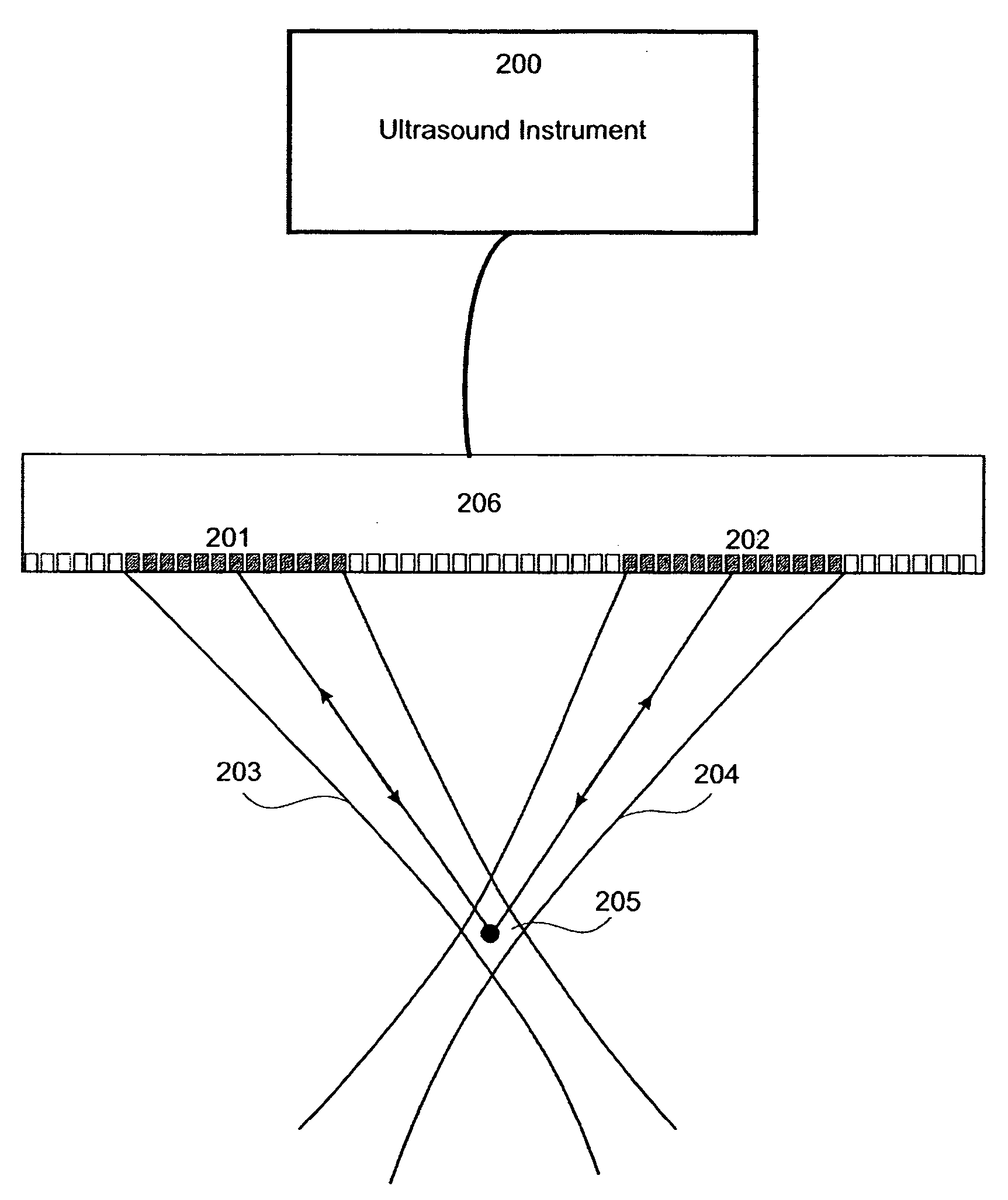
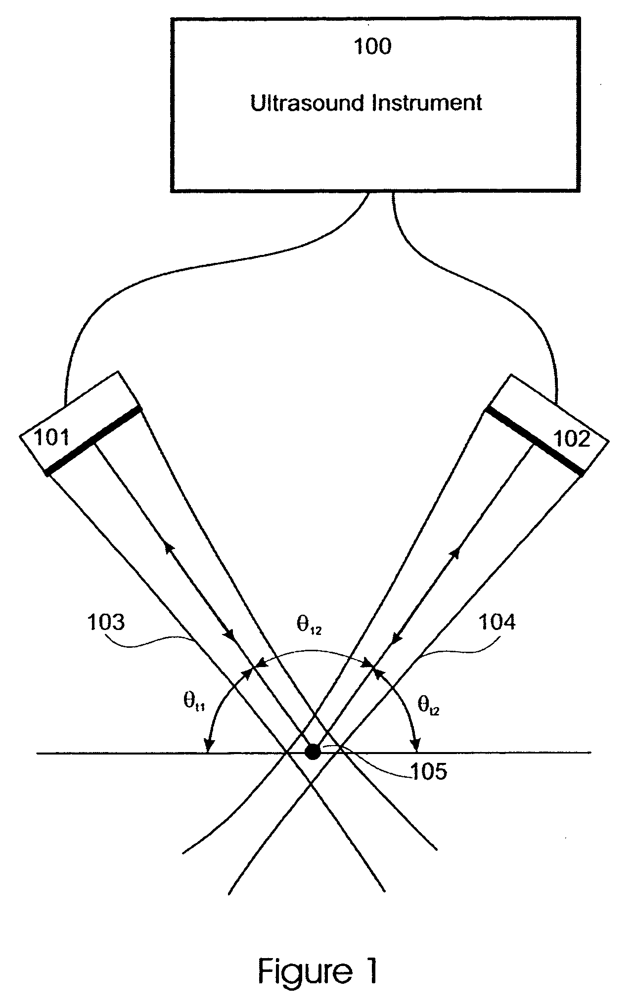
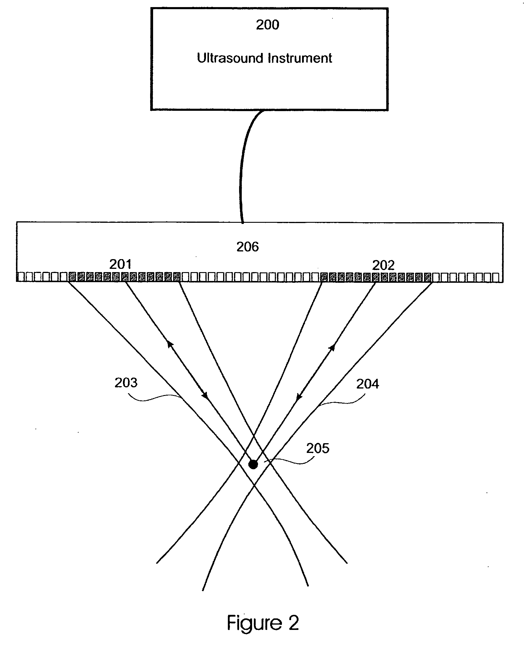
[0026] In the following we describe example embodiments of the invention with reference to the drawings. FIG. 1 shows two ultrasound transducers 101 and 102 that are connected to an ultrasound instrument 100 that allows selectable transmission of ultrasound pulses on each transducer, with selectable reception of the scattered signal on each transducer, independent of the transducer selected for transmission. The transducers can be directed at an angle towards each other, where θt represents the direction of the transmit beam and θtr is the angle between the transmit beam and the receive beam. In the Figure we have θt=θt1 when transmitting on Transducer 1 (101) and θt=θt2 when transmitting on Transducer 2 (102). We denote the beam 103 from Transducer 1 as Beam 1, and the beam 104 from Transducer 2 as Beam 2. The beams intercept in a region labeled 105 in FIG. 1. The angle between Beam 1 and Beam 2 is indicated as θ12 in FIG. 1. When different beams are used to transmit and receive on...


PUM


Abstract

A method for characterizing ultrasound scatterers in soft tissue, wherein scattered signals are used to eliminate the absorption attenuation of an ultrasound wave from estimated parameters and to obtain directional scattering information. The scattered signals are obtained from either multiple regions where one region is used as a reference or multiple scattering directions, creating known reference signals from the same scattering region. The method provides new ultrasound parameters for the characterization and contrast enhancement of tissue structures in ultrasound imaging, such as tumor structures, ischemia of a myocardial wall and / or plaque compositions in vascular atheroma. The method of the invention can be used with various arrangements of ultrasound transducers, particularly switched linear arrays.

Description

RELATED APPLICATIONS [0001] This application claims priority from U.S. Provisional Patent Application Ser. No. 60 / 534,417 which was filed on Jan. 6, 2004.BACKGROUND OF THE INVENTION [0002] 1. Field of the Invention [0003] The present invention, relates to characterization of ultrasound scatterers in soft tissue. The method eliminates the effect of unknown ultrasound absorption between the transducer and the scatterers, and produces local scattering parameters of the tissue and their frequency dependence. [0004] 2. Description of the Related Art [0005] Ultrasound back scatter imaging is a widely used imaging modality for diagnosis of many diseases of humans and animals. However, at present the method is used mainly to visualize anatomic structures, blood velocities, movements, and shear elasticity of tissue, and there is a further need for improved characterization of the scattering tissue structures with dimensions below the resolution in the anatomic image. [0006] Transmitting on o...

Claims


Application Information

Patent Timeline
IPC IPC(8): A61B8/00
CPCA61B8/481
Inventor ANGELSEN, BJORN A.J.JOHANSEN, TONNI F.
Owner ANGELSEN BJORN A J
Learn More