Medical instrument for suction and irrigation, and method for its production

a technology for medical instruments and irrigation, applied in the field of medical instruments for suction and irrigation, can solve the problems of less flexural stability of individual tubes, difficult handling of instruments, and wear, and achieve the effect of easy production

Inactive Publication Date: 2005-08-18
KARL STORZ GMBH & CO KG
View PDF24 Cites 29 Cited by
  • Summary
  • Abstract
  • Description
  • Claims
  • Application Information

AI Technical Summary

Benefits of technology

[0009] It is an object of the invention to improve a medical instrument of the type mentioned at the outset so that the shaft, while being easy to produce, has a compact cross section for a combined suction and irrigation channel.

Problems solved by technology

On the one hand, individual tubes have less flexural stability, and, on the other hand, they each have to be individually sealed off from the outside by suitable sealing measures, for example 0-ring seals, which are subject to wear.
The arrangement of an irrigation tube and a suction tube inserted one inside the other also has the disadvantage that, in the suction tube and in the thin irrigation tube, there is no room for insertion of an endoscope, unless the cross section chosen for the whole shaft is of a considerable size, which is undesirable however in the field of minimally invasive surgery performed through very small incisions in the body.
In addition, the individual tubes have to be assembled before use of the instrument and disassembled before the instrument is cleaned, which makes handling of the instrument difficult.
In this design, although the irrigation channel and the suction channel are integrally connected to one another, a shaped shaft of this kind is relatively complicated to produce since it can only be made in an extrusion process.

Method used


Image

  • Medical instrument for suction and irrigation, and method for its production
  • Medical instrument for suction and irrigation, and method for its production
  • Medical instrument for suction and irrigation, and method for its production

Examples


Embodiment Construction

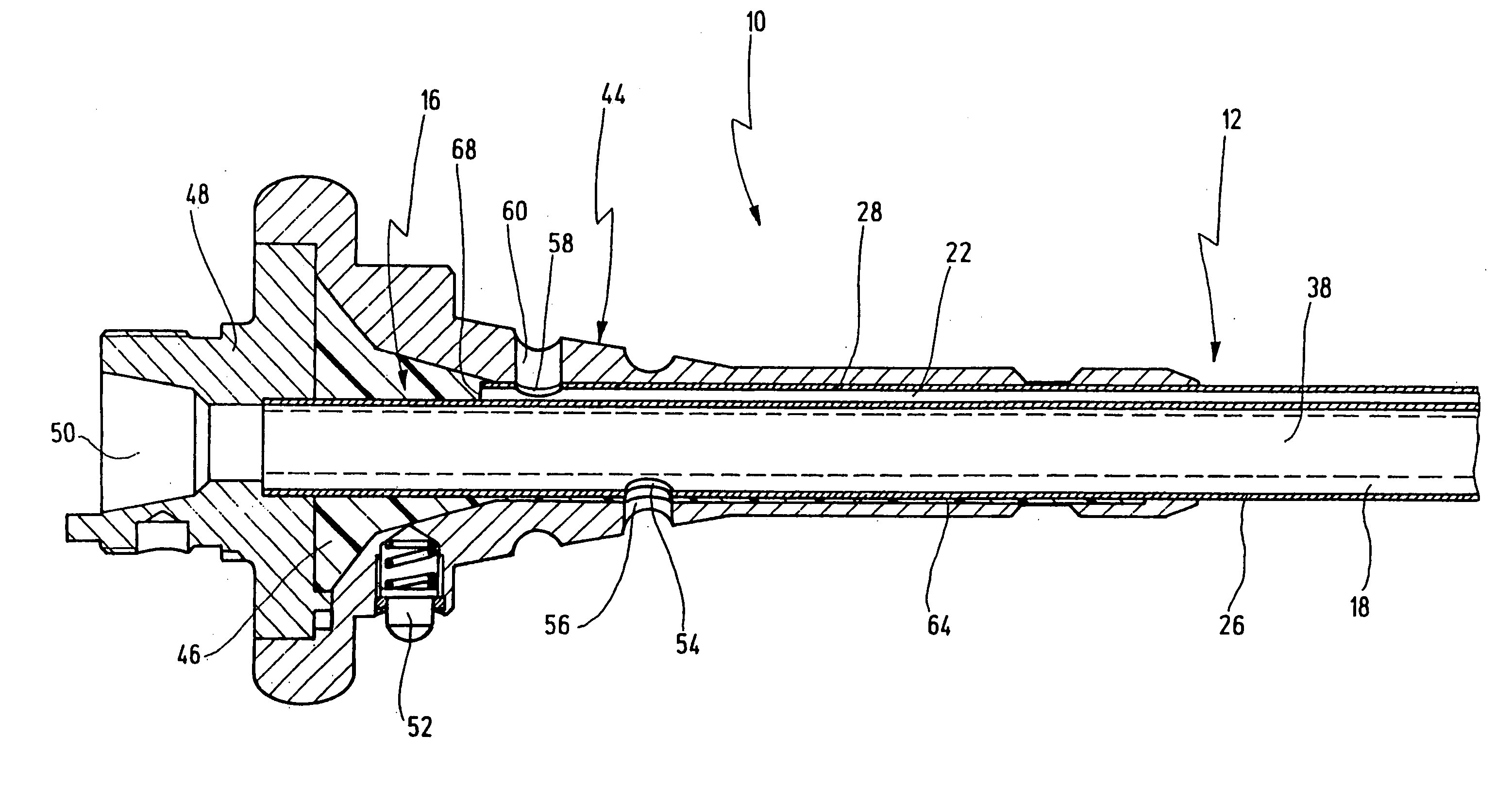
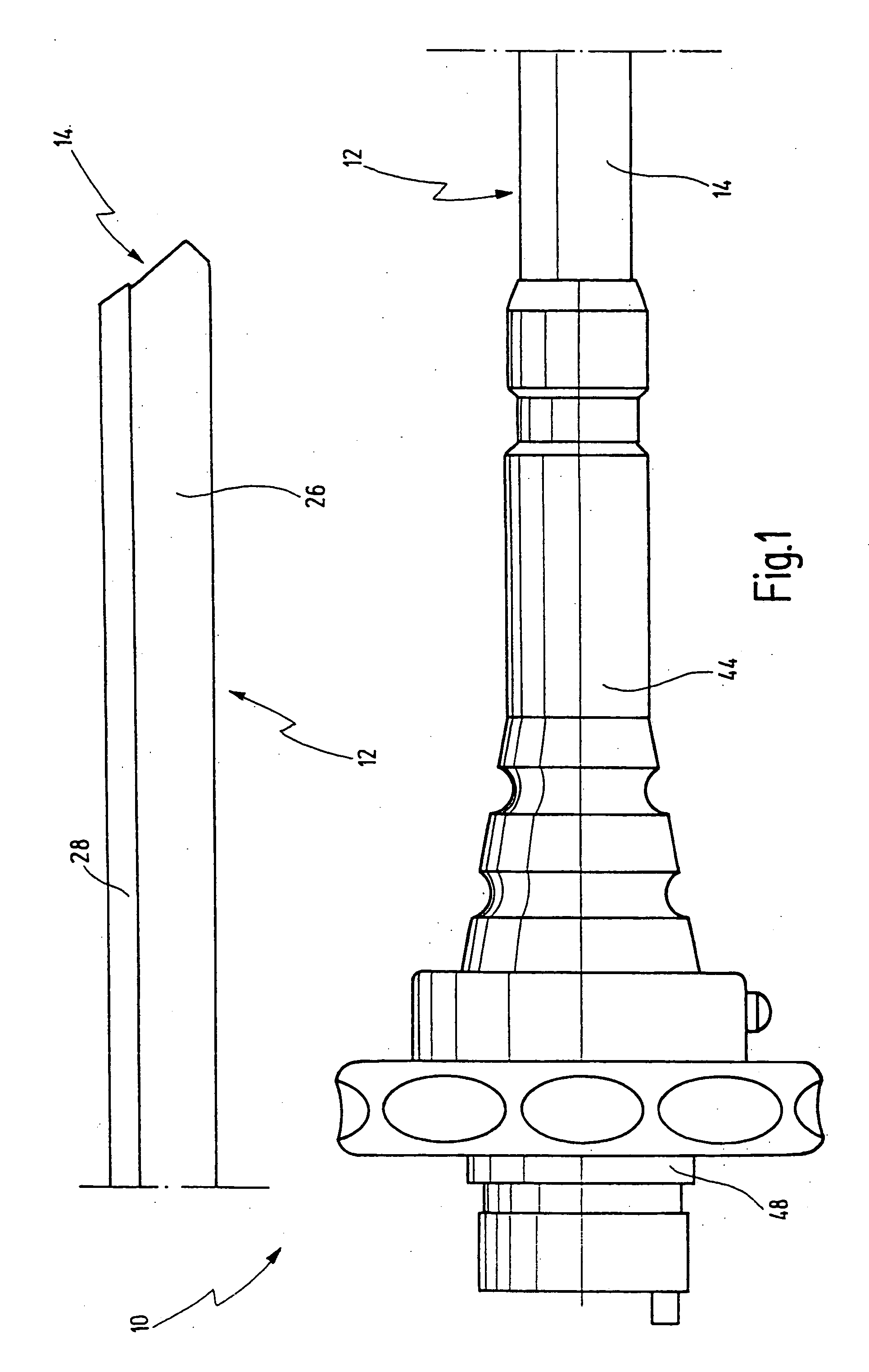
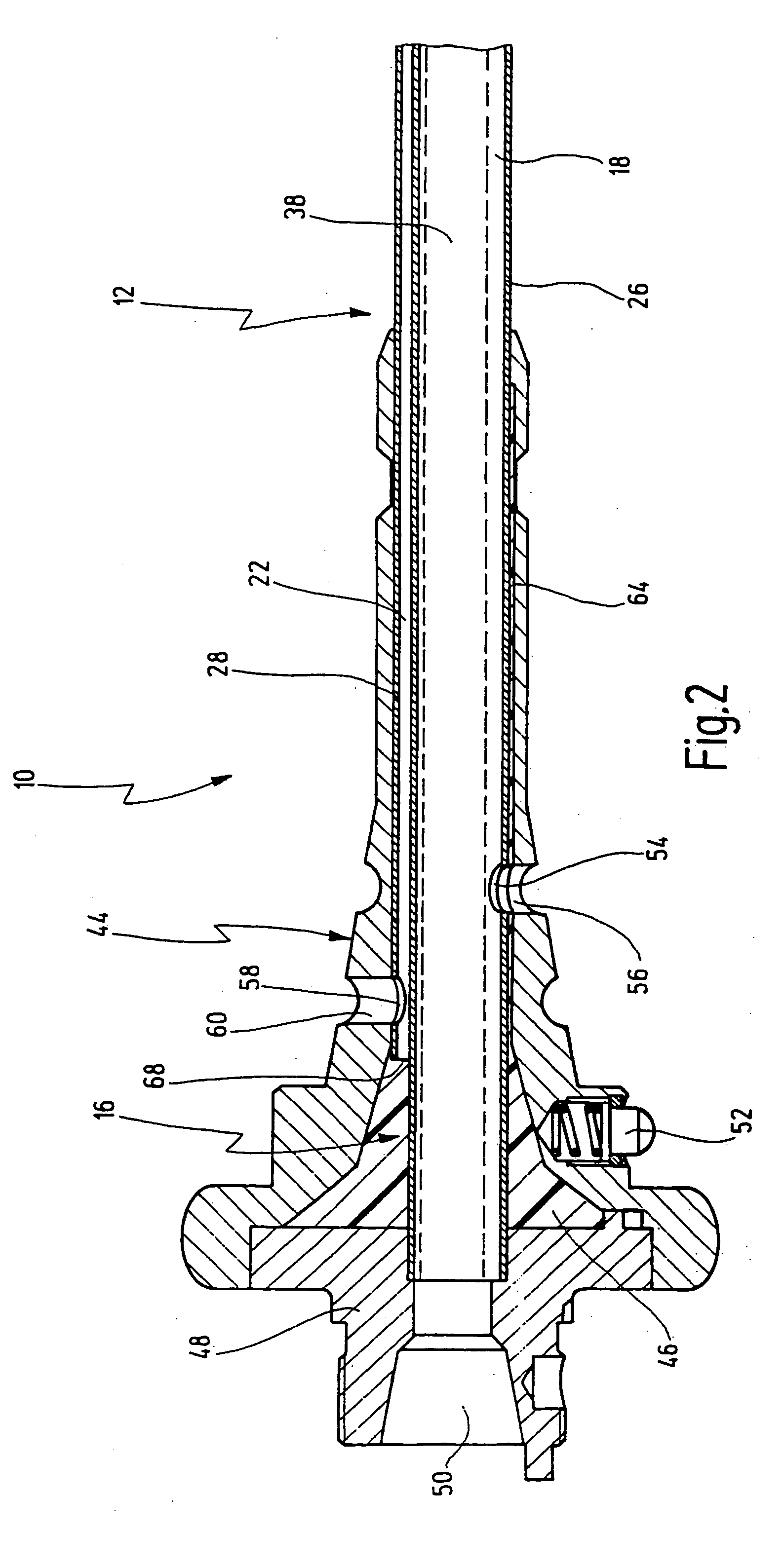
[0060] In FIG. 1, a medical instrument for suction and irrigation is designated overall by reference number 10 and shown in two partial views. The upper partial view in FIG. 1 shows a distal portion of the instrument 10, and the lower partial view shows a proximal portion of the instrument 10 contiguous to the distal portion.

[0061] In surgical procedures, particularly in the field of minimally invasive surgery, the instrument 10 is used for delivering irrigation fluid to an operating site and for suctioning fluids and tissue residues from the operating site. The instrument 10 also permits visual monitoring through an endoscope, as will be described below.

[0062] The instrument 10 has an elongate shaft 12 with a distal end 14 and a proximal end 16 (cf. FIG. 2).

[0063] The shaft 12 has a first channel 18 which serves as suction channel and which accordingly has a suction opening 20 at the distal end 14 of the shaft 12.

[0064] The shaft 12 also has a second channel 22 which is separat...


PUM


Abstract

A medical instrument for suction and irrigation comprises an elongate shaft with a first channel serving as suction channel and with a second channel serving as irrigation channel, the shaft having a first tube which is closed in cross section and in which one of the channels is present. The shaft has a second tube which is open in cross section along its length and is placed with its open lengthwise side on an outside face of the first tube and secured sealingly thereon, the other channel being formed in the space between the outside face of the first tube and an inside face of the second tube. A method for production of the instrument is also described.

Description

CROSS REFERENCE TO RELATED APPLICATIONS [0001] The present application is a continuation of pending International patent application PCT / EP2003 / 009025 filed on Aug. 14, 2003 which designates the United States, and which claims priority of German patent application 102 45 009.9 filed on Sep. 20, 2002.BACKGROUND OF THE INVENTION [0002] The invention relates to a medical instrument for suction and irrigation, having an elongate shaft with one channel serving as suction channel and with another channel serving as irrigation channel. [0003] The invention further relates to a method for producing such a medical instrument. [0004] An instrument of the kind mentioned above is known from the company brochure produced by the German company Karl Storz GmbH & Co. KG, “STORZ Karl Storz-Endoskope”, volume entitled “Laparoskopie”, 3rd edition 2 / 99, page IS-ACC 5 A. [0005] When performing surgical procedures on the human or animal body, such an instrument is used to irrigate the operating site with...

Claims


Application Information

Patent Timeline
Patent Type & Authority Applications(United States)
IPC IPC(8): A61B1/12A61M1/00
CPCA61B1/00071A61B1/00091A61B1/00094A61M1/0084A61B1/12A61B1/126A61M1/0058A61B1/00135A61M1/85A61M1/77
Inventor SCHMIDBERGER, JOCHENEFINGER, ANDREAS
Owner KARL STORZ GMBH & CO KG
Why Eureka
Try Eureka