Percutaneously placed prosthesis with thromboresistant valve portion

a technology of thrombosis resistance and prosthesis, which is applied in the field of prosthesis with thrombosis resistance valve portion, can solve the problems of inability to be easily compressed or collapsed for delivery, and achieve the effect of preventing or limiting the reflux of blood

Inactive Publication Date: 2005-08-18
COOK INC
View PDF20 Cites 408 Cited by
  • Summary
  • Abstract
  • Description
  • Claims
  • Application Information

AI Technical Summary

Benefits of technology

[0006] The foregoing problem is solved by the present prosthetic valve system comprising a valve mechanism having a substantially fixed-diameter support structure or frame of a first diameter sized for intravascular delivery and one or more expandable stents or other anchoring support structures attached to or integral with the valve mechanism frame, preferably located at both ends of the device. The valve support housing or body would be sized so as to fit inside a delivery sheath that could be introduced into the vein by percutaneous (Seldinger) technique. The expandable portions would be sized so that in the collapsed condition (e.g., to the first diameter), the prosthesis would fit inside the delivery sheath. When the system is deployed or expelled from the delivery sheath inside a vessel, the stents would expand to the vein inside diameter and a

Problems solved by technology

Because depositing carbon on the valve components results in a valve and support mechanism that is substan

Method used


Image

  • Percutaneously placed prosthesis with thromboresistant valve portion
  • Percutaneously placed prosthesis with thromboresistant valve portion
  • Percutaneously placed prosthesis with thromboresistant valve portion

Examples


Embodiment Construction

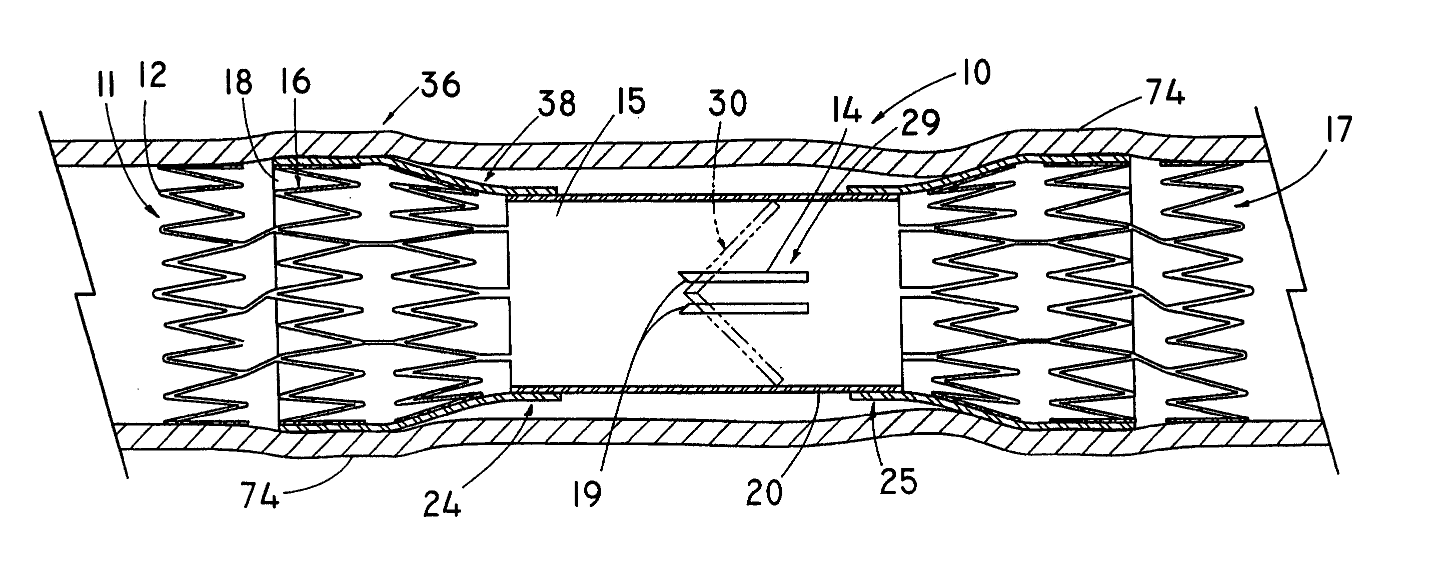
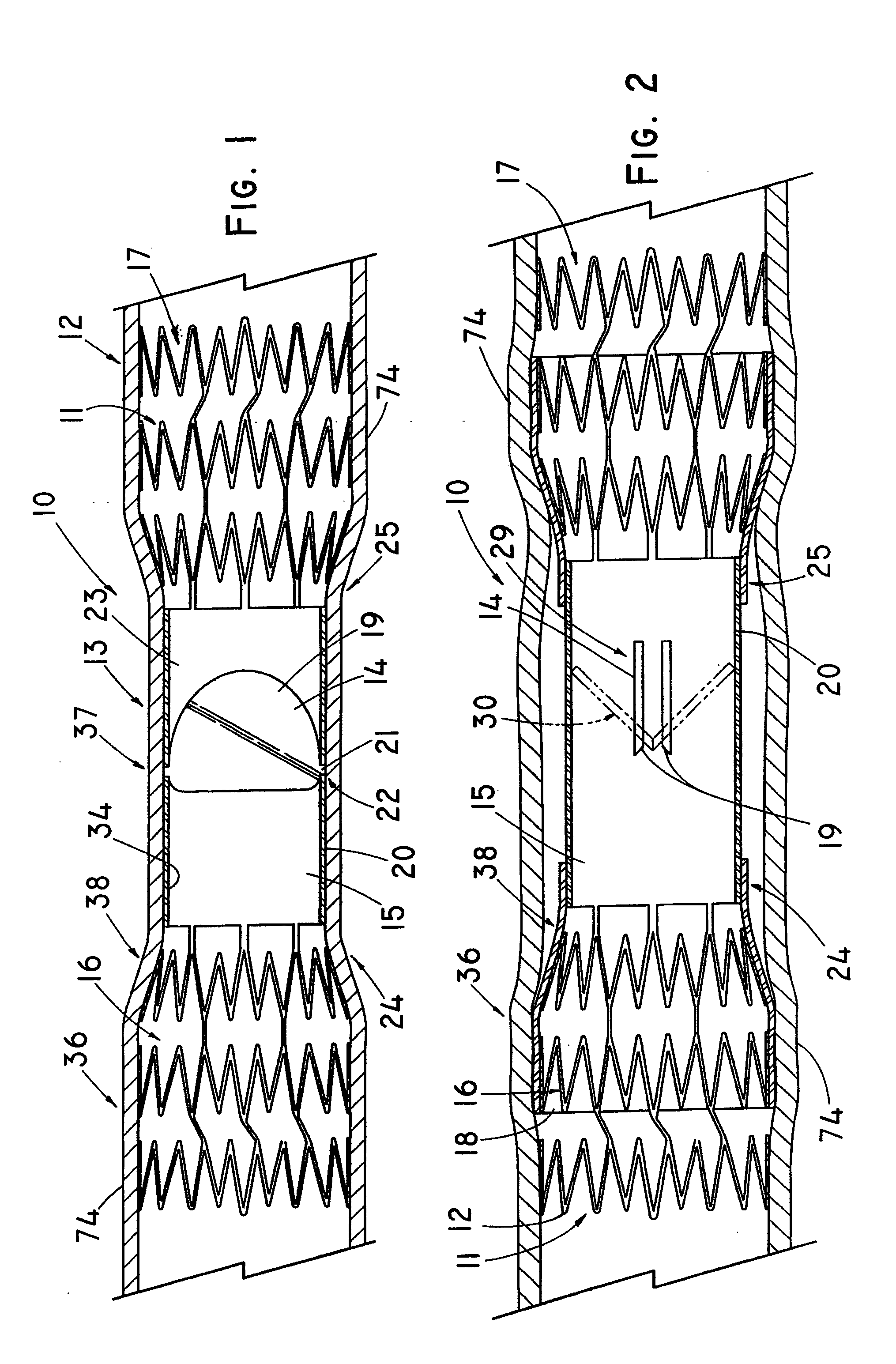
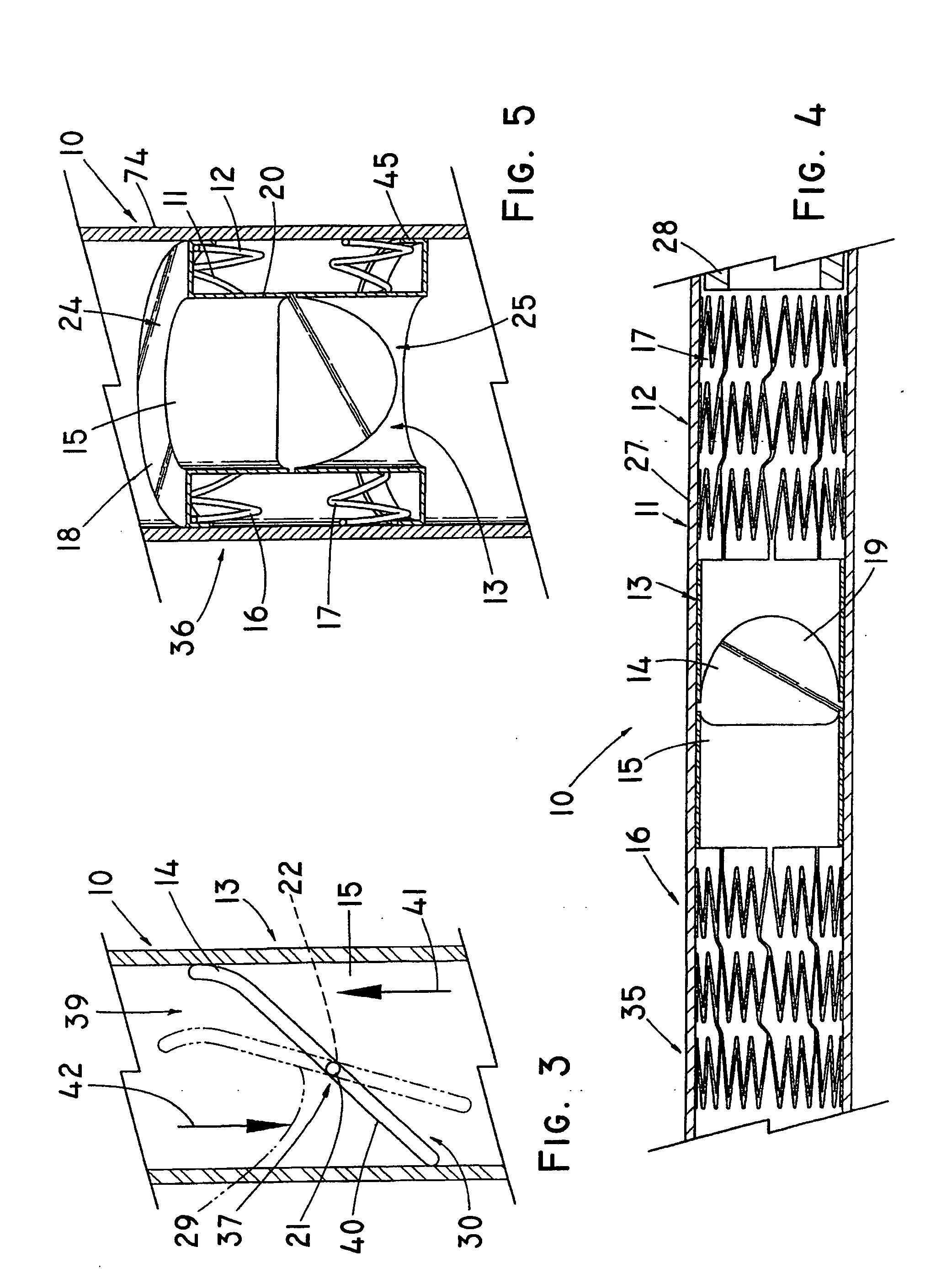
[0030]FIGS. 1-23 depicted a series of embodiments of the present invention of an implantable prosthesis 10, such as an artificial venous or heart valve that includes a support structure 11 comprising one or more anchoring portions 12 configured for engaging the vascular wall, and a valve portion 13 comprising a valve-closing mechanism 14, such as one or more sealing elements, and a valve support housing 15 that comprises a substantially rigid material such that the valve portion 13 or valve support housing 15 has limited collapsibility and thus, relies on the anchoring portion(s) 12 to expand and fully engage the vessel wall to anchor the prosthesis 10 thereagainst. Barbs (not shown) may further serve to help anchor the prosthesis at the implantation site. The valve portion 13 includes either an outer diameter sufficiently small for delivery through a delivery member 27, whereby the anchoring portion provide the necessary radial expansion to engage the vessel; or the valve portion 1...


PUM


Abstract

A venous valve prosthesis having a substantially non-expandable, valve portion comprising a valve-closing mechanism, such as a pair of opposing leaflets; and an anchoring portion, such as one or more self-expanding frames or stents that are expandable to anchor the prosthesis at the implantation site. In one embodiment, the rigid valve portion includes a deposition of material such as pyrolitic carbon to reduce the thrombogenecity of the blood-contacting surfaces. The anchoring portions preferably include a covering, such as a tubular construct of synthetic or collagen-derived material (such as a bioremodelable ECM material), which attaches about the support structure such that blood flow is directed through the valve mechanism as it transitions from the larger diameter anchoring portion to the intermediate, smaller-diameter portion of the prosthesis. In another embodiment, the valve support housing and valve-closing elements are delivered in a collapsed, folded, and/or dissembled state sized for delivery, then manipulated in situ to the second expanded configured following deployment.

Description

CROSS-REFERENCE TO RELATED APPLICATIONS [0001] This application claims priority of provisional application Ser. No. 60 / 543,753, filed Feb. 11, 2004.TECHNICAL FIELD [0002] This invention relates to prosthetic valves percutaneously placed in the vascular system of mammals to augment or replace the function of the natural valves. This invention relates primarily to venous valves which would be percutaneously placed in the veins of the legs to replace the function of diseased or otherwise non-functioning venous valves. BACKGROUND OF THE INVENTION [0003] Chronic venous insufficiency is essentially caused by venous hypertension and chronic venous stasis caused by valvular incompetence. As a result, the height of the blood column from the lower legs to the heart becomes longer, resulting in increased pressure in the veins of the legs. The resulting increase in pressure causes the veins to further dilate and the remaining valves to become incompetent. The disease progresses from varicose ve...

Claims


Application Information

Patent Timeline
IPC IPC(8): A61F2/06A61F2/24
CPCA61F2/2403A61F2/2418A61F2/2424A61F2/2475A61F2230/008A61F2220/005A61F2220/0058A61F2230/0054A61F2230/0078A61F2220/0016
Inventor OSBORNE, THOMAS A.CASE, BRIAN C.FLAGLE, JACOB A.HOFFMAN, GRANT T.
Owner COOK INC
Why Eureka
Try Eureka