
System for limiting reactive torque in powertrains

a technology of reactive torque and powertrain, which is applied in the field of vehicle powertrains, can solve the problems of large inertia, difficult to reduce the reactive force of the powertrain, and the powertrain often has considerable effective inertia, etc., and achieves the reduction or elimination of reactive forces, the effect of limiting the reactive torque of the powertrain and simplifying the structure of the powertrain

Inactive Publication Date: 2005-08-18
FORD GLOBAL TECH LLC
View PDF16 Cites 27 Cited by
  • Summary
  • Abstract
  • Description
  • Claims
  • Application Information

AI Technical Summary

Benefits of technology

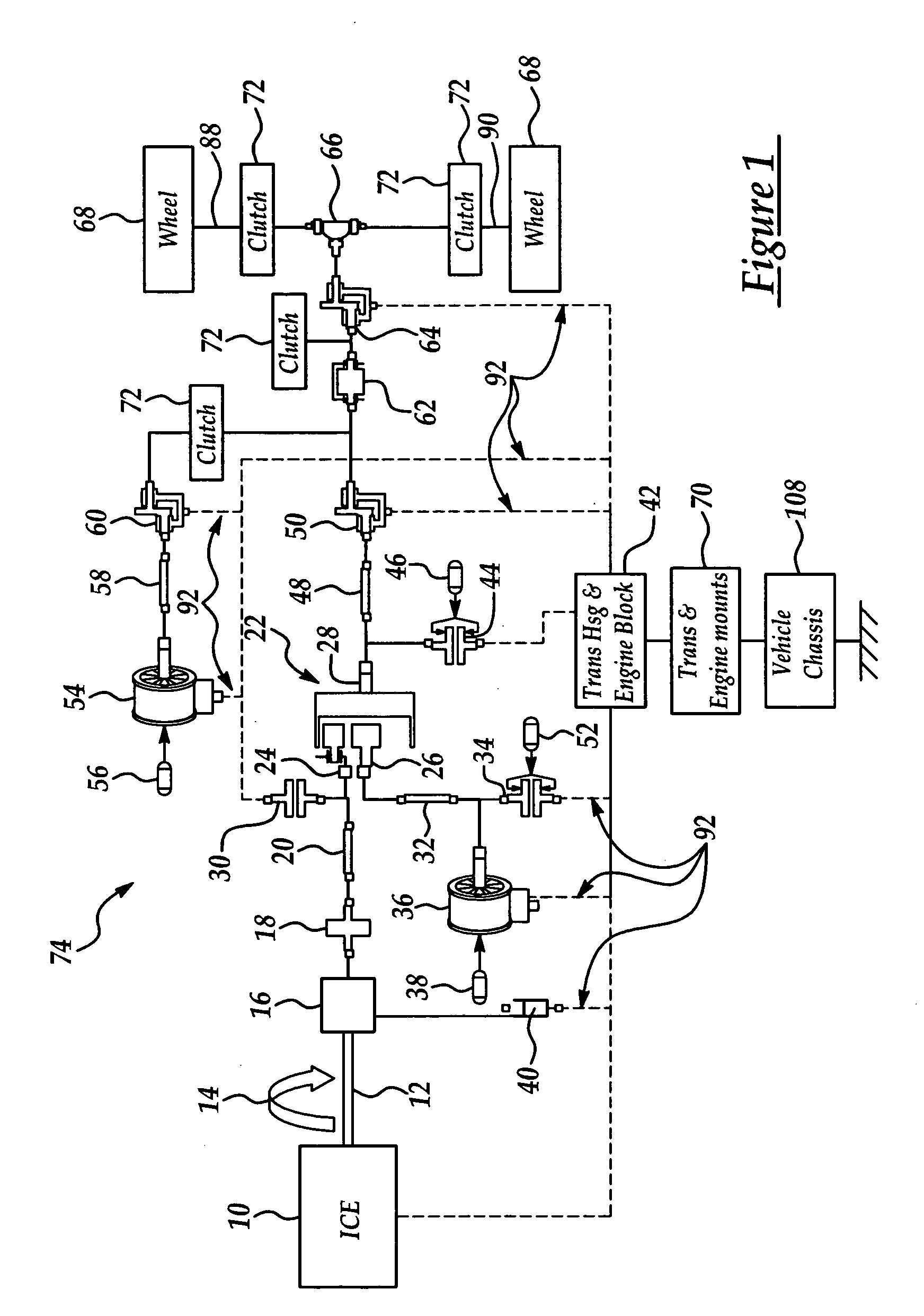
[0007] One advantage of the invention lies in providing a system for limiting reactive torque in powertrains produced by high braking forces applied to traction wheels. The inventive system reduces or eliminates these reactive forces through the use of relatively simple powertrain components such as a slip clutch which partially disconnects the wheels from the driveline during sudden braking events. An important advantage of the invention is that the control system is passive, in that it is directly and automatically activated by reactive torque generated by the sudden braking event, and does not require event or condition sensors to initiate the disconnect process. Moreover, when the sudden braking event ends, the system automatically and immediately reconnects the wheels to the powertrain. A further advantage of the present system resides in its compatibility with a wide range of HEV configurations and powertrain geometries, and the simplicity of its components. Another feature of the invention is that while the system limits undesirable levels of reactive torque, it permits lesser levels of negative torque to be transmitted from the wheels to the driveline during regenerative braking modes of powertrain operation.
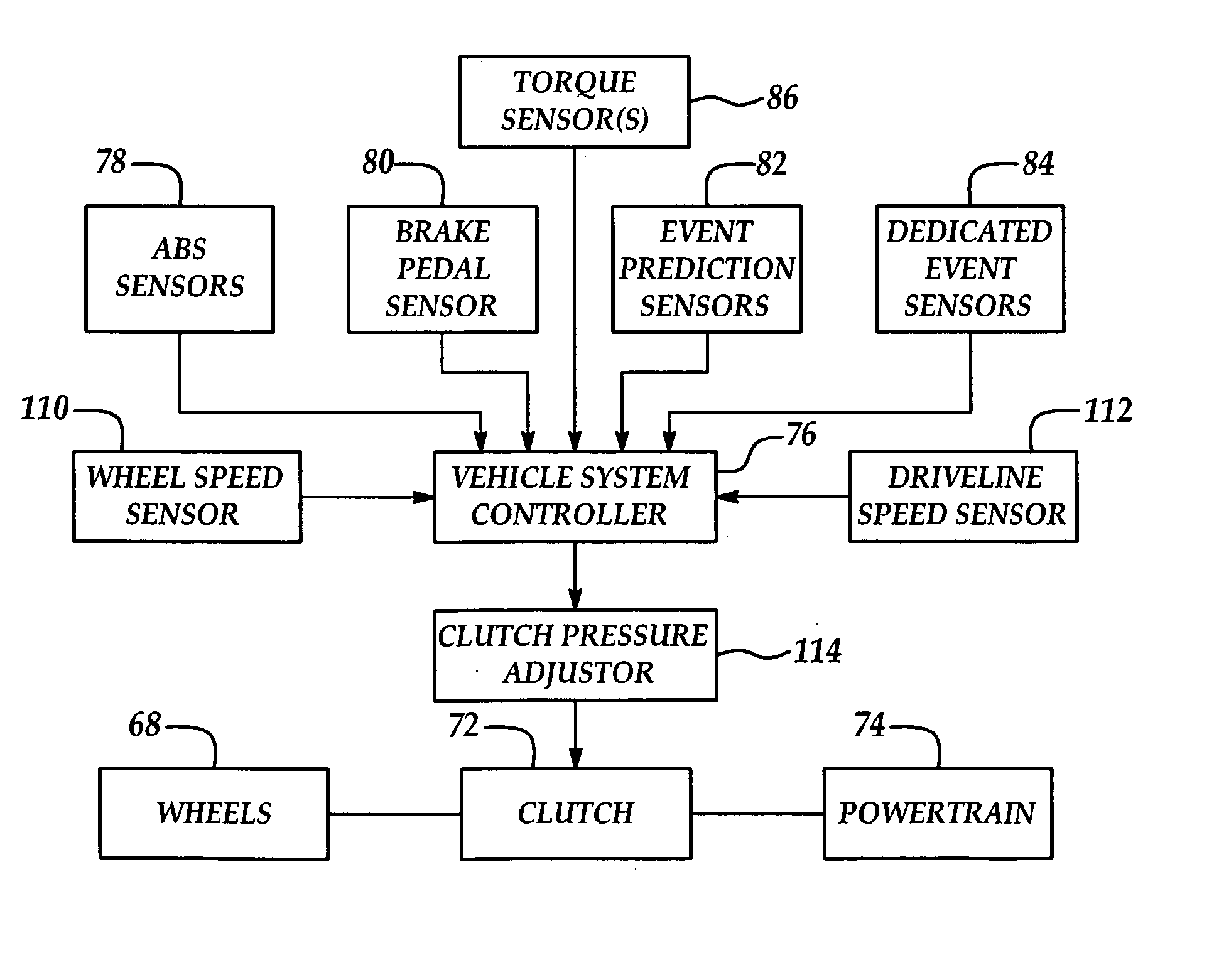
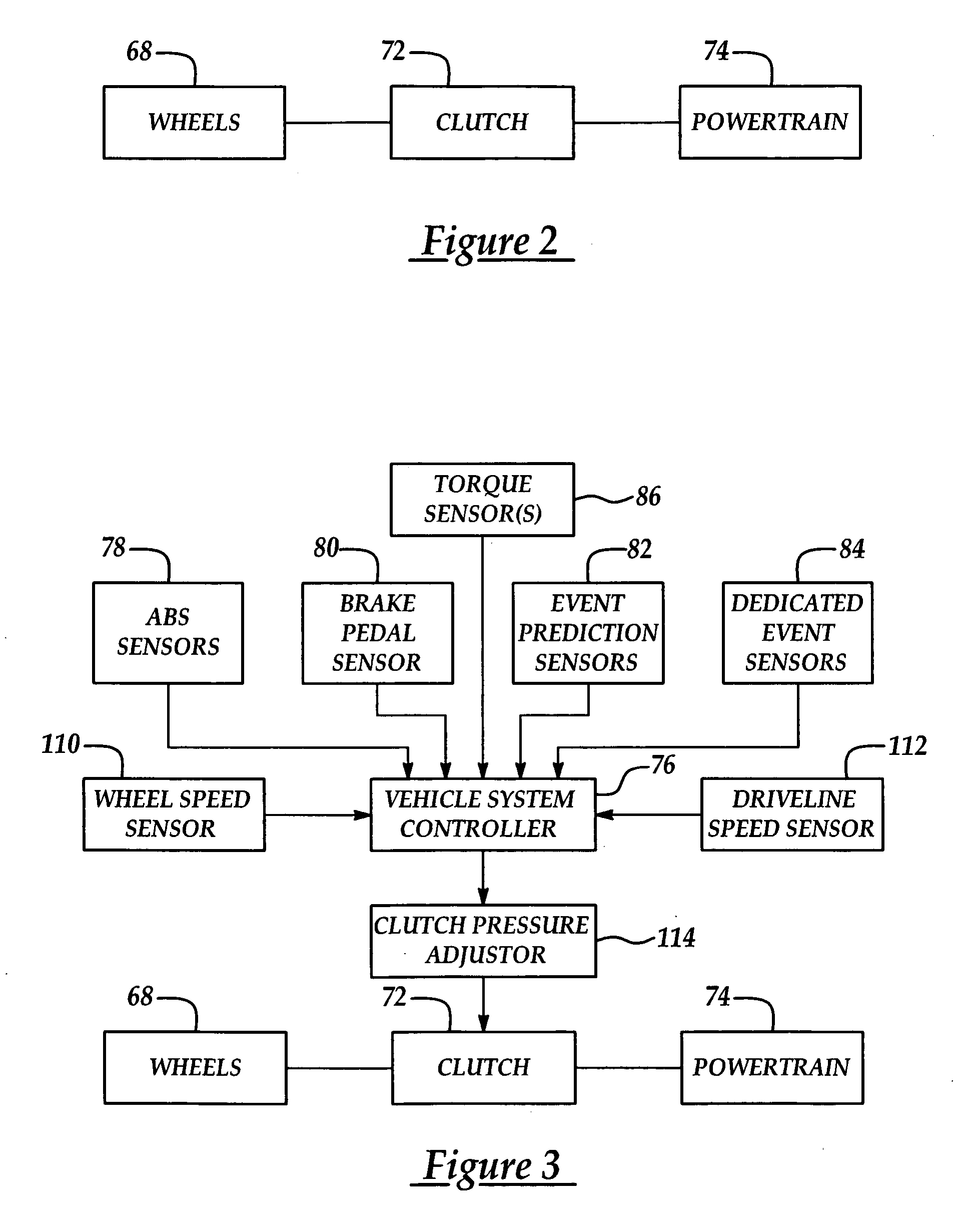
[0008] In accordance with a first embodiment of the invention, a method is provided for controlling a vehicle powertrain during a sudden braking event, which includes limiting the amount of reactive wheel torque transmitted from the wheels to the powertrain. The amount of the reactive torque transmitted to the powertrain is limited by using a slip clutch in the driveline which automatically slips when the reactive torque applied to it reaches a preselected value. In an alternate embodiment, the clutch pressure is adjustable, allowing control of the amount of reactive torque that is transmitted from the wheels through the clutch to the powertrain.
[0009] Other features and advantages of the present invention may be better understood by considering the following details of a description of a preferred embodiment of the invention. In the course of this description, reference will frequently be made to the attached drawings.

Problems solved by technology

As a result, HEV powertrains often possess considerable effective inertia at the wheels compared to conventional ICE powertrains.
This is due in part to the potentially large inertia of the hybrid motor devices, as well as the significant gearing from motor to wheels that is often employed.
Powertrains possessing relatively high effective inertias such as those of HEVs, result in certain problems that require solutions.
For example, the application of braking force to the vehicle's traction wheels during a sudden braking event, may result in a very rapid angular momentum change in the powertrain.
Specifically, a rapid deceleration of the traction wheels during braking results in a counter-torque being transmitted from the traction wheels back through the driveline.
This reaction torque is transmitted through the gearing mechanisms to the transmission housing, and can have deleterious effects on powertrain and driveline components, particularly under sudden braking conditions, such as when the vehicle's ABS system is activated.
Fluctuating driveline torques, which are transmitted through the vehicle's halfshafts, act to accelerate or decelerate the wheels, thereby potentially reducing the effectiveness of the vehicle's ABS system which is not designed to take into consideration dynamic powertrain reaction torque.
Additionally, fluctuating driveline torque can produce noise, vibration and harshness (NVH) in the powertrain and driveline, and in some cases can even cause the vehicle's ABS to excite the vehicle powertrain at its natural frequency, thereby imposing additional undesirable stress on the powertrain.

Method used


Image

  • System for limiting reactive torque in powertrains
  • System for limiting reactive torque in powertrains
  • System for limiting reactive torque in powertrains

Examples


Embodiment Construction

[0017]FIG. 6 shows a generic architecture for a hybrid vehicle system 134, to which the present invention may be applied. The system 134 includes a primary power source 123, such as a gasoline, diesel or other gas fuel supply, coupled to a primary power generating system 125, such as an internal combustion engine. The primary power generating system 125 generates a primary drive torque that is transmitted to the vehicle's driveline 132 via power transmission assembly 129. The power transmission assembly 129 can be a conventional manual, automatic or continuously variable automotive transmission, or other equivalent gearing mechanism for transmitting mechanical power produced by the primary power generating system 125. The system 134 further includes a secondary power source 133, such as a battery, ultracapacitor, hydraulic accumulator or other energy storage device, and secondary power generating system 131, such as one or more electric machines or other torque generating devices, f...


PUM


Abstract

A control system limits reactive torque in a powertrain that is generated when braking force is applied to traction wheels during a sudden stop or other sudden braking event. The reactive torque generated at the traction wheels is prevented from being transmitted upstream through the driveline and powertrain by using a slip type clutch in the driveline to limit the upstream transfer of the reactive wheel torque. The clutch is directly actuated by the reactive torque and therefore does not require special controls or monitoring systems to sense the braking event. The clutch pressure may be automatically adjusted in response to certain operating conditions or events, thereby adjusting the point at which the clutch begins to slip due to reactive wheel torque.

Description

FIELD OF THE INVENTION [0001] This invention generally relates to vehicle powertrains, and deals more particularly with a system for limiting reactive torque developed in a powertrain due to sudden changes in the inertia of powertrain components. BACKGROUND OF THE INVENTION [0002] Environmental concerns and the need for fuel conservation has spurred the development of new hybrid propulsion systems for vehicles. Hybrid electric vehicle (HEV) powertrains for example, typically include electric traction motors, high voltage electric energy storage systems, and modified transmissions. Electric energy storage systems include batteries and ultra capacitors. Primary power units for these systems may include spark ignition engines, compression ignition direct injection (e.g., diesel) engines, gas turbines and fuel cells. [0003] HEV powertrains are typically arranged in series, parallel or parallel-series configurations. With parallel-series arrangements, multiple motors operating in multipl...

Claims


Application Information

Patent Timeline
IPC IPC(8): B60K6/48B60K17/02B60K17/04B60K28/16B60W10/02B60W20/00F16D7/02F16D43/21F16D48/06F16H35/10G06F19/00
CPCB60K6/48Y02T10/6221B60L2260/14B60W10/02B60W2520/26F16D48/06F16D2500/10412F16D2500/1066F16D2500/3065F16D2500/30816F16D2500/3115F16D2500/31426F16D2500/50293F16D2500/70406B60K28/165Y02T10/62
Inventor TOBLER, BILLTILLER, MICHAELBOWLES, PAUL
Owner FORD GLOBAL TECH LLC
Learn More