N-phase interface tracking method utilizing unique enumeration of microgrid cells

Inactive Publication Date: 2005-08-18
CHEVROU USA INC
View PDF22 Cites 28 Cited by
  • Summary
  • Abstract
  • Description
  • Claims
  • Application Information

AI Technical Summary

Benefits of technology

[0016] It is an object of the present invention to provide a method for simulating fluid flow that can easily h

Problems solved by technology
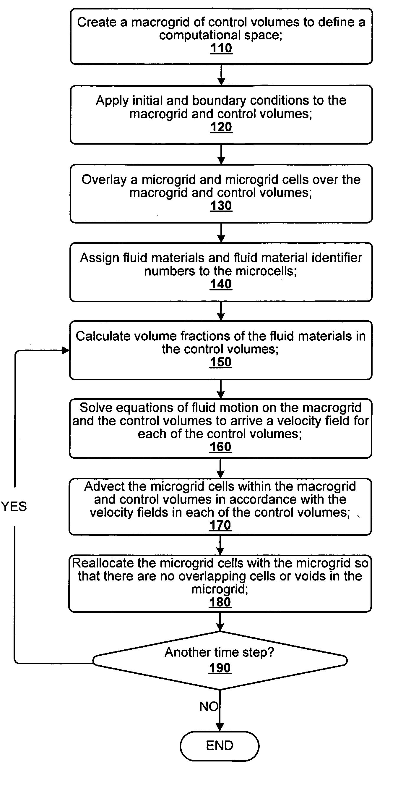
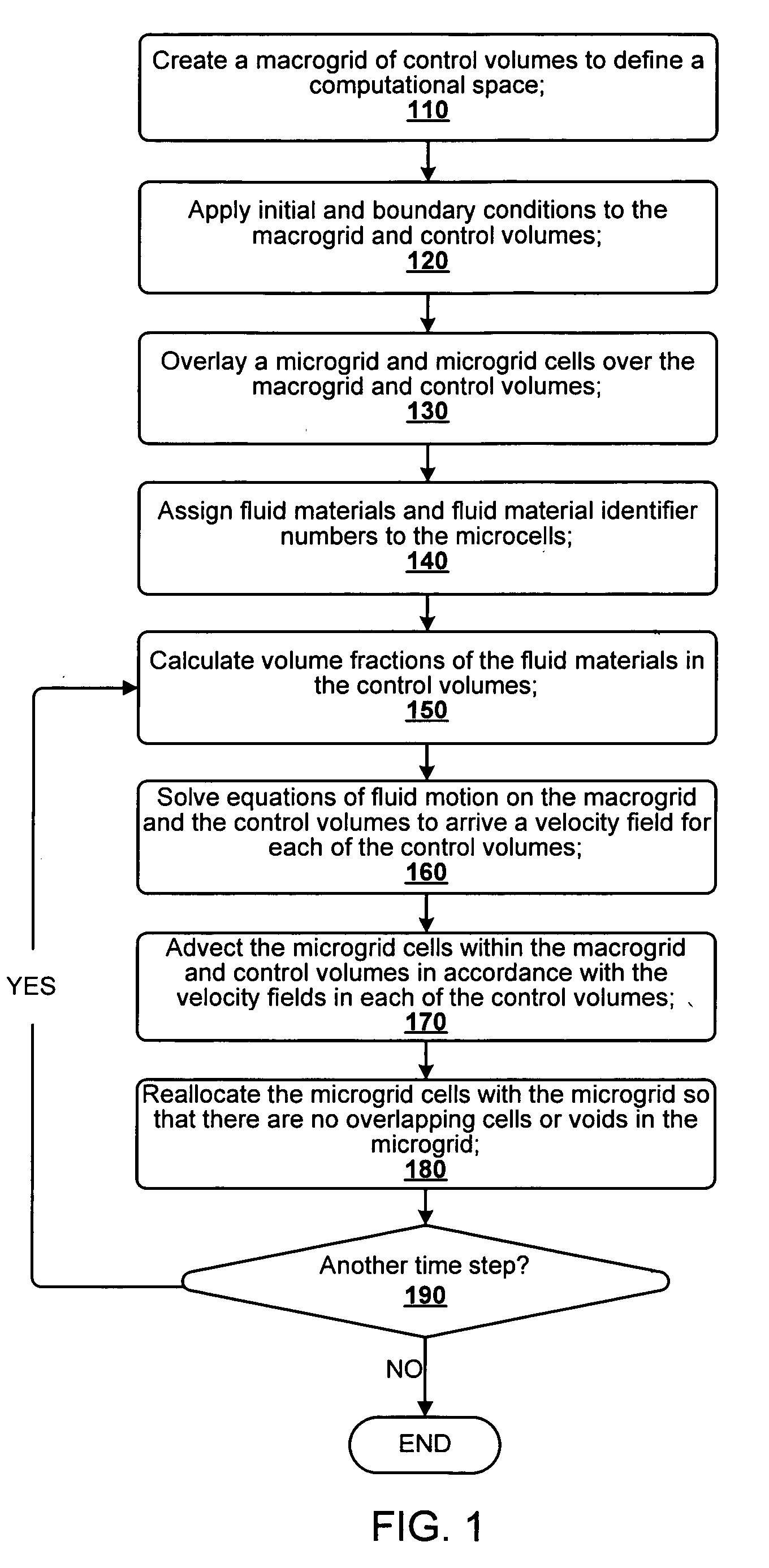
However, there is still no generalized method presently developed that allows for the numerical simulation of the dynamic movement of three or more fluid materials and their interfaces.
However these methods are restricted to cases involving only two materials.
However, no one to date has addressed the issue of uniquely identifying and tracking, with a single or multiple concentration function(s) Ci, three or more materials.
In addition, when multiple equation sets are used as possi

Method used


Image

  • N-phase interface tracking method utilizing unique enumeration of microgrid cells
  • N-phase interface tracking method utilizing unique enumeration of microgrid cells
  • N-phase interface tracking method utilizing unique enumeration of microgrid cells

Examples


computational example 1

[0074] Circulating rectangular cavity flow offers a rigorously investigated, complicated flow pattern for the reader's review. In this example, the cavity is initialized with a stratified pattern of three similar materials, differing only in prime designation not material properties. In this manner the similarity of the flow form is qualified by literature comparison to a single fluid flow, as well as to illustrate the use of three numerically distinct materials in the microgrid algorithm.

[0075] Rhee et. al. (1984) and Freitas (1986) describe a similar recirculating cavity flow such that given the schematic of FIG. 8, a plate drives a continuous shear motion from front to back at the top of the cavity. FIG. 8 also illustrates the formation of secondary eddies in three of the four corners of the cavity along a center plane. FIG. 9 is a photograph of Rhee's experimental flow along a similar plane for comparison. FIG. 10 is a rendering of the microgrid algorithm output for the three s...

example 2

[0078] As an example, this same simulation is offered with 126×126 computational mesh and a microgrid cell mesh of 2×2 (¼ of the microgrid resolution shown in the above simulation of FIG. 10) in a side by side comparison at time step=210. This time step is chosen because it shows adequate detail of all the eddy features.

[0079] Because the algorithm employs an additive and collective response measure to the effect of velocity over multiple time steps, the more coarse the microgrid cell refinement is, the less immediate physical response one can see in areas of relatively low velocity. Similarly, because of the block-like movement of microgrid cells, to capture areas of high thinning, microgrid cell size must be reduced. This is most evident in the middle layer, where material should form thin trails in response to the shear motion of the primary circulation cell. Also, while the overall response of the system at coarse micromesh is good, it may be noted that interfacial smoothness a...

example 3

[0081] The results shown in FIG. 12 utilize a 126×126 computational mesh with an 8×8 microgrid mesh. FIG. 13 is an artistic rendering of the 6 materials in the same view at time step=120.

[0082] While in the foregoing specification this invention has been described in relation to certain preferred embodiments thereof, and many details have been set forth for purposes of illustration, it will be apparent to those skilled in the art that the invention is susceptible to alteration and that certain other details described herein can vary considerably without departing from the basic principles of the invention.


PUM


Abstract

A method for tracking N fluid materials and their associated interfaces during simulated fluid flow is disclosed. A microgrid cell methodology is embedded on a regular macrogrid to subdivide and then tag fluid materials in a computational system preferably using a prime numbering algorithm. The motion of microgrid cells is tracked based on local velocity conditions, rectifying small anomalies by a coupled evaluation of local volume fraction fields and global mass conservation. Volume fractions can be calculated at any time step via an evaluation of the prime locations so that average cellular density and viscosity values can be regularly updated.

Description

TECHNICAL FIELD [0001] This invention relates generally to methods for the simulation of multiphase fluid flows, and more particularly, to those methods which track interfaces between immiscible fluids. BACKGROUND OF THE INVENTION [0002] The study of interfacial flow is a broad topic of interest in many different research disciplines. Physicists, biologists, engineers and other scientists all share a stake in accurate representation of interfacial position. Whether pipeline flow of crude oil mixtures, cellular disruption or the development of galaxies is to be modeled, interfacial movement intimately influences calculations by accounting for a redistribution of local density functions. In general, the problems of interest have as a common element the requirement to resolve through numerical simulation the complex flow patterns that result from the flow of immiscible (or semi-immiscible) fluids. [0003] Published works dating from the 1960's until now relate an ever-improving understa...

Claims


Application Information

Patent Timeline
IPC IPC(8): G06F17/10G06F17/50
CPCG06F2217/16G06F17/5009G06F30/20G06F2111/10
Inventor FREITAS, CHRISTOPHER J.CLARKE, MARY ANN
Owner CHEVROU USA INC
Why Eureka
Try Eureka