Method for making power supplies smaller and more efficient for high-power PCs

a power supply and high-power pc technology, applied in the field of power management, can solve the problems of power supply loss of approximately 20-30%, system size, heat and noise, bulky and cumbersome, etc., and achieve the effect of power supply capacity, system performance reduction, and power supply capacity

Active Publication Date: 2005-08-18
MICROSOFT TECH LICENSING LLC
View PDF11 Cites 47 Cited by
  • Summary
  • Abstract
  • Description
  • Claims
  • Application Information

AI Technical Summary

Benefits of technology

[0008] According to another feature, a notification may be provided that the capacity of the power supply is reaching a maximum level and system performance will be reduced.
[0009] According to another aspect of the invention, there is provided a computing device having an operating system or If an small power supply is used, for example a travel power supply for notebooks, the system may for example operate at the equivalent or similar to the conventional maximum battery life modes other control program or process and a power supply adapted to report a capacity of the power supply to the operating system. The device includes a central processing unit, a graphics processing unit, a hard disk drive, and random access memory. The operating system monitors a load on the power supply to determine if the load is above a predetermined threshold, and reduces power consumption of predetermined components within the computing device in order to maintain power consumption of the computing device below the capacity of the power supply.

Problems solved by technology

Power supplies for desktop and mobile PCs contribute significantly to the overall size, heat and noise of a system.
However, the actual power drawn by the system while running normal office desktop applications is typically 70-150 W, including a power supply loss of approximately 20-30%.
Another example is notebooks, which tend to ship with large external power supplies that are designed to run the notebook in worst case scenarios, making them bulky and cumbersome when traveling.
Another related problem is efficiency.
When efficiency is lowered, unnecessary heat is generated through losses in the PSU.

Method used


Image

  • Method for making power supplies smaller and more efficient for high-power PCs
  • Method for making power supplies smaller and more efficient for high-power PCs
  • Method for making power supplies smaller and more efficient for high-power PCs

Examples


Embodiment Construction

[0017] Exemplary Computing Environment

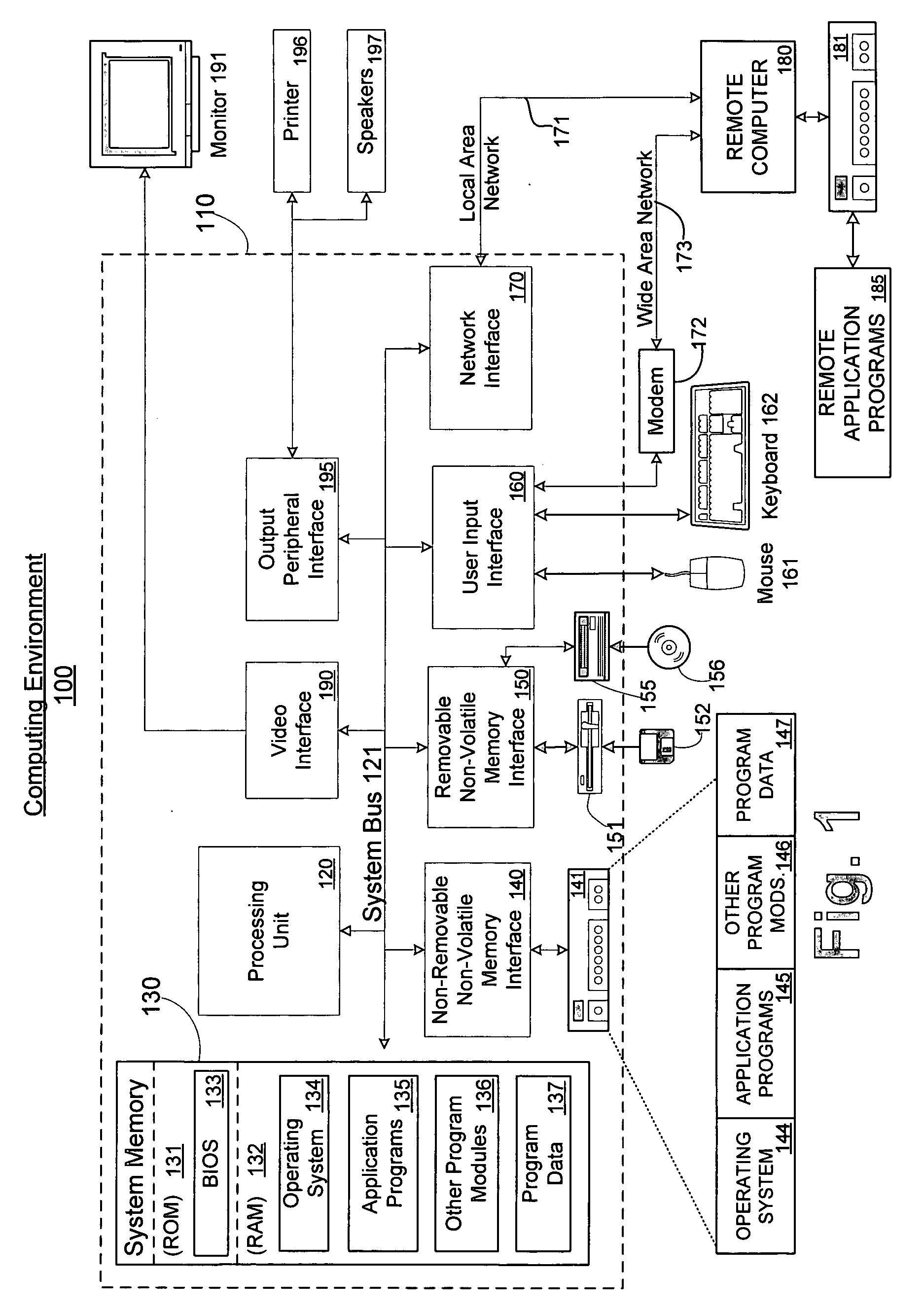
[0018]FIG. 1 illustrates an example of a suitable computing system environment 100 in which the invention may be implemented. The computing system environment 100 is only one example of a suitable computing environment and is not intended to suggest any limitation as to the scope of use or functionality of the invention. Neither should the computing environment 100 be interpreted as having any dependency or requirement relating to any one or combination of components illustrated in the exemplary operating environment 100.

[0019] The invention is operational with numerous other general purpose or special purpose computing system environments or configurations. Examples of well known computing systems, environments, and / or configurations that may be suitable for use with the invention include, but are not limited to, personal computers, server computers, hand-held or laptop devices, multiprocessor systems, microprocessor-based systems, set top bo...


PUM


Abstract

Systems and methods for reducing the size of a power supply in a computing device by monitoring activities to maintain the load on the power supply below a predetermined threshold. Through a set of software drivers, various components are placed into low power states in order to reduce the load on the power supply. The methods allow manufacturers to utilize smaller power supplies that are better fitted for the actual operating conditions of the computing device, rather than a large power supply designed for worst case conditions.

Description

FIELD OF THE INVENTION [0001] This invention generally relates to the field of power management. More particularly, this invention relates to a system and method of reducing the size of a power supply in a computing device by providing a mechanism by which the power supply and the operating system communicate to mange power consumption of components within the computing device. BACKGROUND OF THE INVENTION [0002] Power supplies for desktop and mobile PCs contribute significantly to the overall size, heat and noise of a system. For example, a typical desktop PC intended for office includes a 250 W-300 W power supply (PSU). However, the actual power drawn by the system while running normal office desktop applications is typically 70-150 W, including a power supply loss of approximately 20-30%. If a PC could be delivered with, for example, a 150 W power supply, this would represent a saving in cost for the manufacturer, and a reduction in overall size of the power supply enabling smalle...

Claims


Application Information

Patent Timeline
Patent Type & Authority Applications(United States)
IPC IPC(8): G06F1/26G06F1/32
CPCG06F1/3203G06F1/324G06F1/3265G06F1/3268G06F1/3281Y02B60/1242Y02B60/1217Y02B60/1246Y02B60/1264Y02B60/1285Y02B60/32G06F1/3296Y02D10/00Y02D30/50
Inventor ANDERSON, JASON MICHAELCHANDLEY, ADRIAN MARK
Owner MICROSOFT TECH LICENSING LLC
Why Eureka
Try Eureka