Detector using microchannel plates and mass spectrometer

Active Publication Date: 2005-08-25
JEOL LTD
View PDF1 Cites 17 Cited by
  • Summary
  • Abstract
  • Description
  • Claims
  • Application Information

AI Technical Summary

Benefits of technology

[0018] Accordingly, it is an object of the present invention to provide a detector structure which suppresses di

Problems solved by technology

However, the voltage on the outer fringe of the organic

Method used


Image

  • Detector using microchannel plates and mass spectrometer
  • Detector using microchannel plates and mass spectrometer
  • Detector using microchannel plates and mass spectrometer

Examples


Embodiment Construction

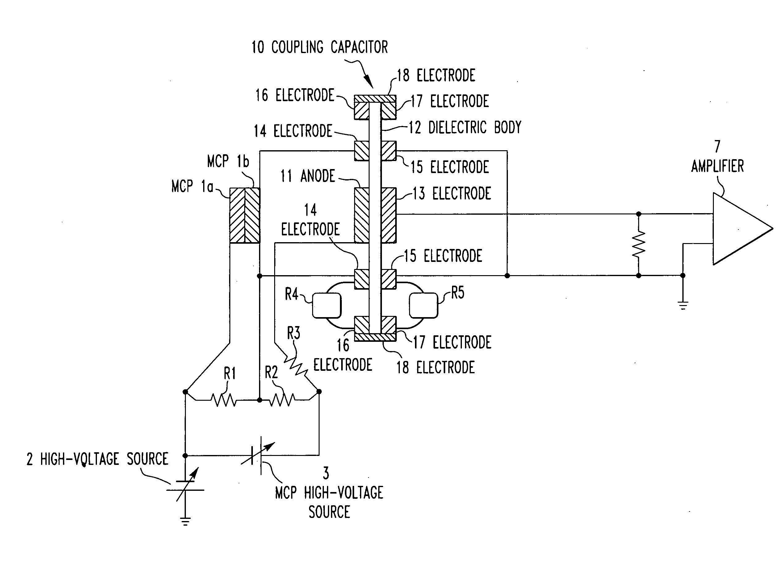
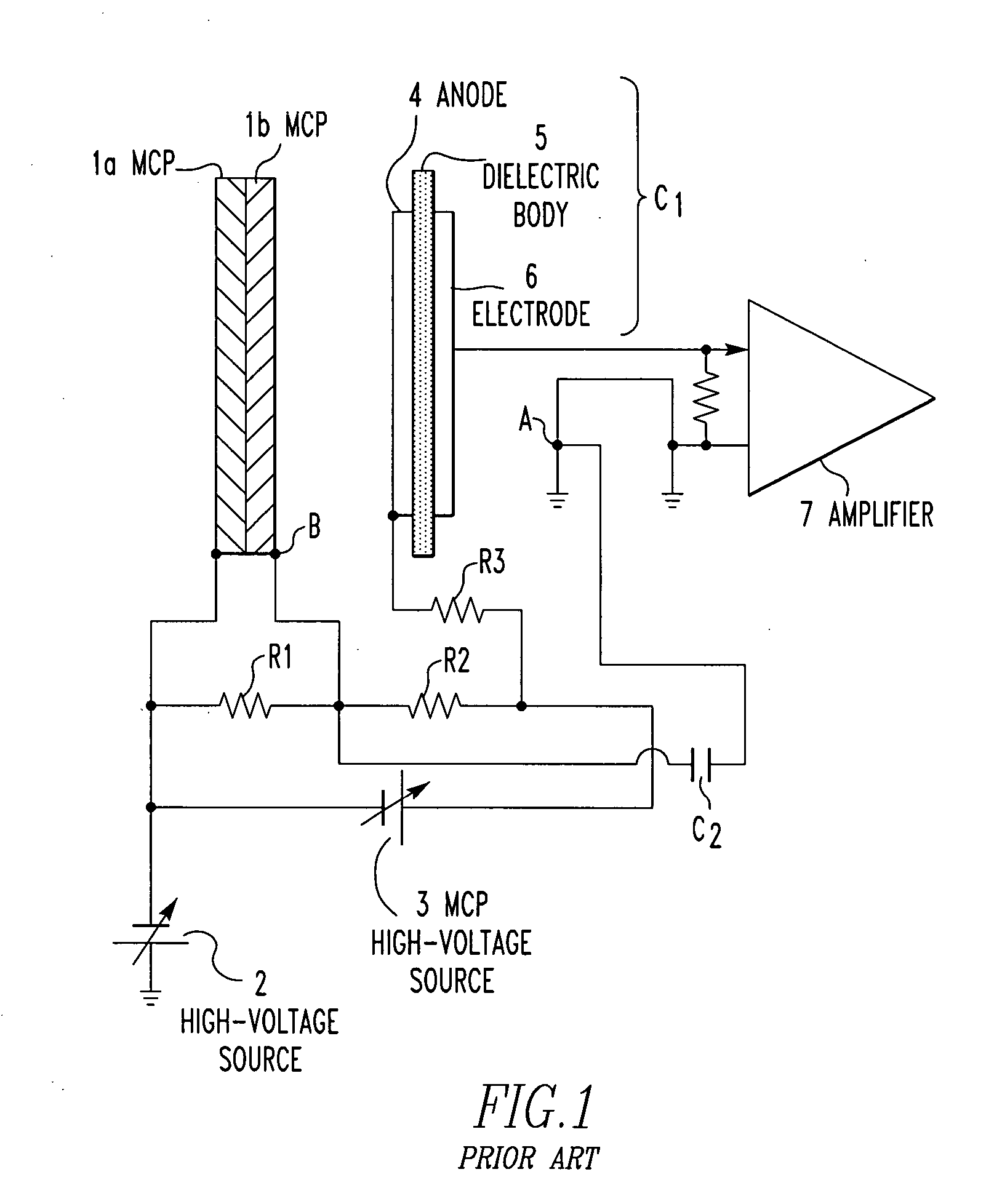
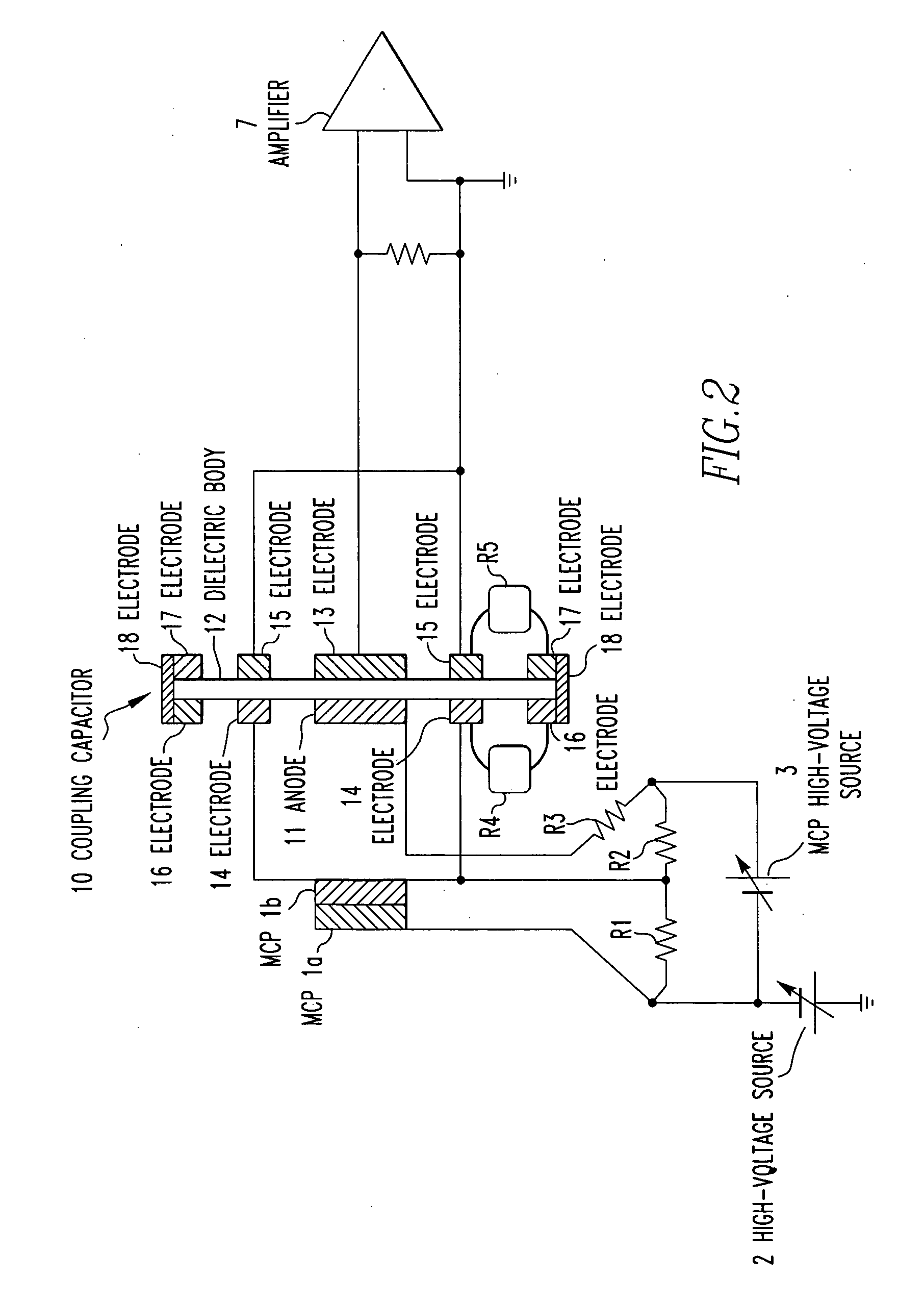
[0025] An embodiment of the present invention is hereinafter described in detail with reference to the drawings. FIG. 2 shows the whole detector including a detector circuit according to the present invention. It is to be noted that like components are indicated by like reference numerals in both FIGS. 1 and 2. In FIG. 2, two microchannel plates (MCPs) 1a and lb are stacked on top of each other in use. A high voltage of −7 kV, for example, is applied from an ion acceleration high-voltage source 2 to the ion incident surface of the MCP 1a.

[0026] Furthermore, a high voltage (e.g., about 2 kV) is applied between the ion incident surface of the MCP assembly consisting of the two superimposed MCPs 1a and 1b and the exit surface from which multiplied electrodes exit from an MCP high-voltage source 3 via a voltage-dividing resistor R1. The voltage source 3 produces a high voltage (e.g., 2.1 kV). As a result, the emissive surface of the MCP 1b is at a potential of −5 kV. In addition, a pot...


PUM


Abstract

A mass spectrometer detector having a coupling capacitor including an anode that is placed at a high potential of say −4.9 kV. An annular electrode is placed outside the anode. A voltage of say −5 kV is applied to the annular electrode. This reduces the potential difference between the anode and the annular electrode, mitigating the electric field. A peripheral electrode is mounted on the outer fringe of a dielectric body and stably held at a potential of say −2.5 kV, for example, by voltage-dividing resistors.

Description

BACKGROUND OF THE INVENTION [0001] 1. Field of the Invention [0002] The present invention relates to a particle detector using microchannel plates for detecting charged particles, such as ions and electrons, and also to a mass spectrometer. [0003] 2. Description of Related Art [0004] Microchannel plates (MCPs) are used to detect very weak ions and electrons and are important as a detector for mass spectrometry. A microchannel plate is fabricated by forming a multiplicity of holes in a glass plate and making a conductive coating on each surface of the plate. Furthermore, an appropriate substance having a high resistance value is applied on the inner surface of each formed hole. [0005] As a result, if a voltage of about 2 kV is applied between the conductive coatings on both sides of the glass plate, a potential gradient is developed between the opposite ends of each hole. A material having high secondary electron emmissivity is selected as the applied resistive substance, and the int...

Claims


Application Information

Patent Timeline
IPC IPC(8): G01T1/28G01T7/00H01J43/00H01J43/12H01J43/24H01L21/027
CPCH01J43/12H01J2237/24435H01J43/246
Inventor SUZUKI, TAKAYUKIKUDOU, NOBUOTAMURA, JUN
Owner JEOL LTD
Why Eureka
Try Eureka