Methods and Apparatus for Generating Strongly-Ionized Plasmas with Ionizational Instabilities

a technology of ionization instabilities and plasmas, which is applied in the direction of vacuum evaporation coatings, coatings, electric discharge lamps, etc., can solve the problems of overheating the electrodes as well as the workpiece in the chamber, temperature gradients in the chamber, and overheating the workpi

Active Publication Date: 2005-08-25
ZOND
View PDF28 Cites 49 Cited by
  • Summary
  • Abstract
  • Description
  • Claims
  • Application Information

AI Technical Summary

Problems solved by technology

Applying high electrical currents through a plasma can result in overheating the electrodes as well as overheating the work piece in the chamber.
However, the cooling can cause temperature gradients in the chamber.
These temperature gradients can cause non-uniformities in the plasma density which can cause non-uniform plasma process.
However, pulsed DC power systems are prone to arcing at plasma ignition and plasma termination, es

Method used


Image

  • Methods and Apparatus for Generating Strongly-Ionized Plasmas with Ionizational Instabilities
  • Methods and Apparatus for Generating Strongly-Ionized Plasmas with Ionizational Instabilities
  • Methods and Apparatus for Generating Strongly-Ionized Plasmas with Ionizational Instabilities

Examples


Embodiment Construction

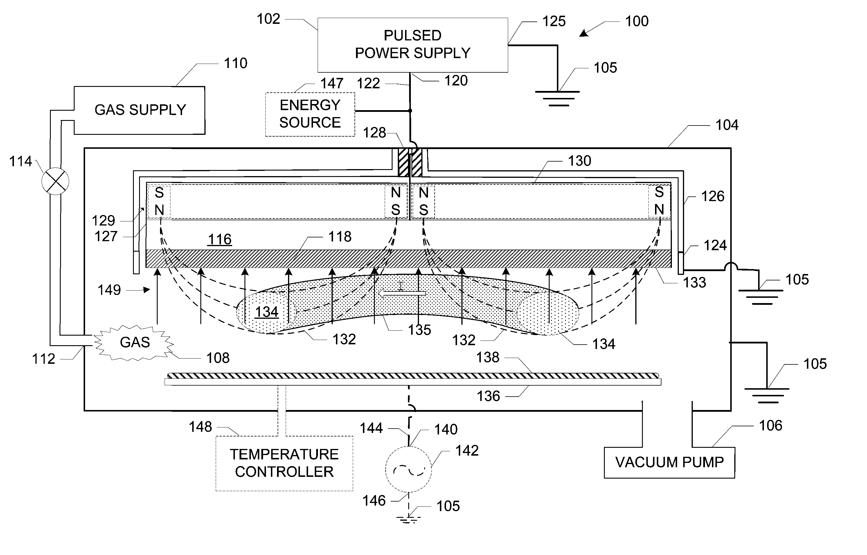
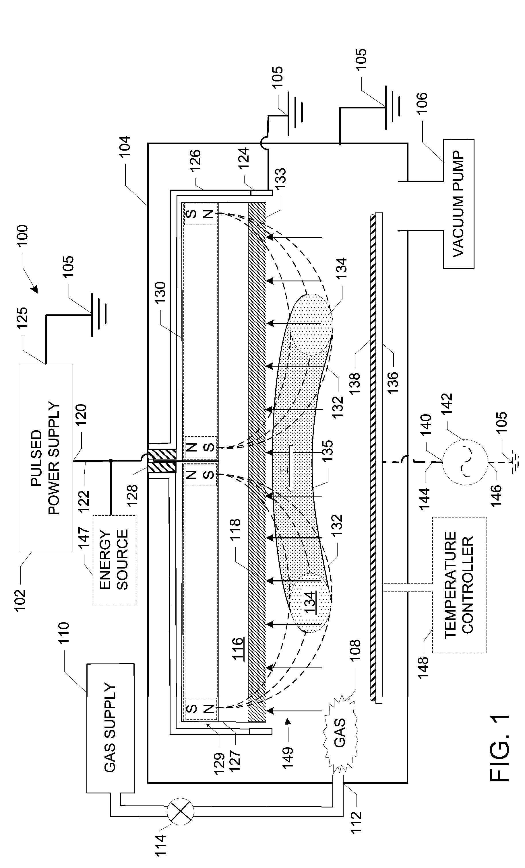
[0018]FIG. 1 illustrates a cross-sectional view of a plasma sputtering apparatus 100 having a pulsed direct current (DC) power supply 102 according to one embodiment of the invention. The plasma sputtering apparatus 100 includes a vacuum chamber 104 for containing a plasma. The vacuum chamber 104 can be coupled to ground 105. The vacuum chamber 104 is positioned in fluid communication with a vacuum pump 106 that is used to evacuate the vacuum chamber 104 to high vacuum. The pressure inside the vacuum chamber 104 is generally less than 10−1 Torr for most plasma operating conditions. A process or feed gas 108 is introduced into the vacuum chamber 104 through a gas inlet 112 from a feed gas source 110, such as an argon gas source. The flow of the feed gas is controlled by a valve 114. In some embodiments, the gas source is an excited atom or metastable atom source.

[0019] The plasma sputtering apparatus 100 also includes a cathode assembly 116. The cathode assembly 116 shown in FIG. 1 ...


PUM

PropertyMeasurementUnit
Timeaaaaaaaaaa
Electric potential / voltageaaaaaaaaaa
Timeaaaaaaaaaa

Abstract

Methods and apparatus for generating strongly-ionized plasmas are disclosed. A strongly-ionized plasma generator according to one embodiment includes a chamber for confining a feed gas. An anode and a cathode assembly are positioned inside the chamber. A pulsed power supply is electrically connected between the anode and the cathode assembly. The pulsed power supply generates a multi-stage voltage pulse that includes a low-power stage with a first peak voltage having a magnitude and a rise time that is sufficient to generate a weakly-ionized plasma from the feed gas. The multi-stage voltage pulse also includes a transient stage with a second peak voltage having a magnitude and a rise time that is sufficient to shift an electron energy distribution in the weakly-ionized plasma to higher energies that increase an ionization rate which results in a rapid increase in electron density and a formation of a strongly-ionized plasma.

Description

BACKGROUND OF INVENTION [0001] A plasma can be created in a chamber by igniting a direct current (DC) electrical discharge between two electrodes in the presence of a feed gas. The electrical discharge generates electrons in the feed gas that ionize atoms thereby creating the plasma. The electrons in the plasma provide a path for an electric current to pass through the plasma. The energy supplied to the plasma must be relatively high for applications, such as magnetron plasma sputtering. Applying high electrical currents through a plasma can result in overheating the electrodes as well as overheating the work piece in the chamber. Complex cooling mechanisms can be used to cool the electrodes and the work piece. However, the cooling can cause temperature gradients in the chamber. These temperature gradients can cause non-uniformities in the plasma density which can cause non-uniform plasma process. [0002] Temperature gradients can be reduced by pulsing DC power to the electrodes. Pul...

Claims


Application Information

Patent Timeline
IPC IPC(8): C23C14/35H01J37/34
CPCC23C14/35H01J37/3455H01J37/3408H01J37/3266
Inventor CHISTYAKOV, ROMAN
Owner ZOND
Why Eureka
Try Eureka