Precipitation effects mitigation at antennae systems

a precipitation effect and antennae technology, applied in the field of instruments, can solve the problems of affecting the operation of microwave radiometers, erroneous high, and general severe degradation of microwave radiometers, and achieve the effects of reducing the number of precipitation effects, and accurate operation

Inactive Publication Date: 2005-08-25
RADIOMETRICS CORP
View PDF4 Cites 10 Cited by
  • Summary
  • Abstract
  • Description
  • Claims
  • Application Information

AI Technical Summary

Benefits of technology

[0012] It is another object of this invention to provide apparatus and methods for mitigation of precipitation effects realized at an antenna system / window of an instrument directly exposed to precipitation events that employs, alone or in combination, a plurality of mechanisms to mitigate such precipitation effects, including high velocity blowers, vibration inducers, surface treatments, and modeling and / or analysis in software or firmware for corrective purposes.
[0013] It is still another object of this invention to provide apparatus and methods for mitigation of precipitation effects realized at an antenna system / window of a microwave radiometer directly exposed to precipitation events to enable accurate operation during precipitation events thus allowing continuation of meteorological measurements through the precipitation events as well as determination of new parameters.
[0014] It is still another object of this invention to provide, for mitigating effects of hydrometeors presented at an instrument antenna system / window directly exposed to precipitation events, an apparatus acting adjacent to the system / window with sufficient force to cause movement of the hydrometeors relative to the system / window.
[0015] It is yet another object of this invention to provide, for mitigating effects of hydrometeors presented at an instrument antenna system / window directly exposed to precipitation events, an apparatus including a mechanism for inducing the movement of the hydrometeors before and / or after hydrometeor contact or formation at the system / window.
[0016] It is another object of this invention to provide an apparatus for mitigating effects of hydrometeors presented at an instrument antenna system / window directly exposed to precipitation events, the apparatus including a relatively high velocity blower mechanism acting adjacent to the system / window with sufficient force to cause movement of the hydrometeors relative to the system / window either or both of before and after hydrometeor contact or formation at the system / window.
[0017] It is still another object of this invention to provide a method for mitigating effects of hydrometeors presented at an instrument antenna system / window directly exposed to precipitation events that includes the steps of sensing hydrometeor presence at the system / window indicating a precipitation event and, responsive thereto, employing at least one mechanism for reliably refining instrument output during the precipitation event.

Problems solved by technology

Heretofore, operation of microwave radiometers has generally severely degraded during precipitation events because of contamination of the radiometer antenna system by hydrometeors (precipitation particles in liquid, ice, or mixed or wetted phase).
Hence, microwave radiometer measurements have not provided meaningful or useful data when made during precipitation events, primarily because liquid water and / or other precipitation products or contaminants on the dielectric window of the antenna system causes erroneously high measurement values.
This inability to operate accurately during precipitation events has caused discontinuity of meteorological measurements and inhibited use of microwave radiometers for determination of parameters such as precipitation rates, duration and event location relative to the antenna.
However, to date, the reliability and accuracy of radiometers during all weather conditions has proven insufficient thereby disqualifying such instruments for significant use as operational weather observation systems.
This deficiency has again been primarily due to the contamination of observations due to precipitation on the antenna system, as well as inadequacy in modeling high liquid content during very wet or precipitating conditions, and inadequacy in modeling scattering of microwave radiation from hydrometeors.
Therefore, use of microwave radiometers has often been limited to field observation during nonprecipitating periods (or, at best, where conditions of extremely light moisture may be present on the antenna window).
Accouterments for such radiometers have been used or suggested for promoting quick drying of the antenna system after it has become wet, but have not addressed the issues of actual use of the radiometer or other such instrument during precipitation events.
This approach, while utilized, has proven problematical due to further contamination from spray and mist created by the system during precipitation events.
Systems utilizing light air flow are not, however, intended for use during precipitation events, nor are they effective during such events to enable accurate readings by the radiometer.
Moreover, such heretofore known or utilized air flow systems have not been effective across the entire dielectric window (drying the top only while neglecting the sides of the window).
Axial flow fans employed by such systems have caused vorticity in the flow, inducing problems at the dielectric window associated with such nonlaminar flow, have been susceptible to back pressure, and have been implemented so that precipitation may be passed through the system and back onto the antenna window.
Such hydrophobic surface treatments alone, however, have not proven to be entirely satisfactory.

Method used


Image

  • Precipitation effects mitigation at antennae systems
  • Precipitation effects mitigation at antennae systems
  • Precipitation effects mitigation at antennae systems

Examples


Embodiment Construction

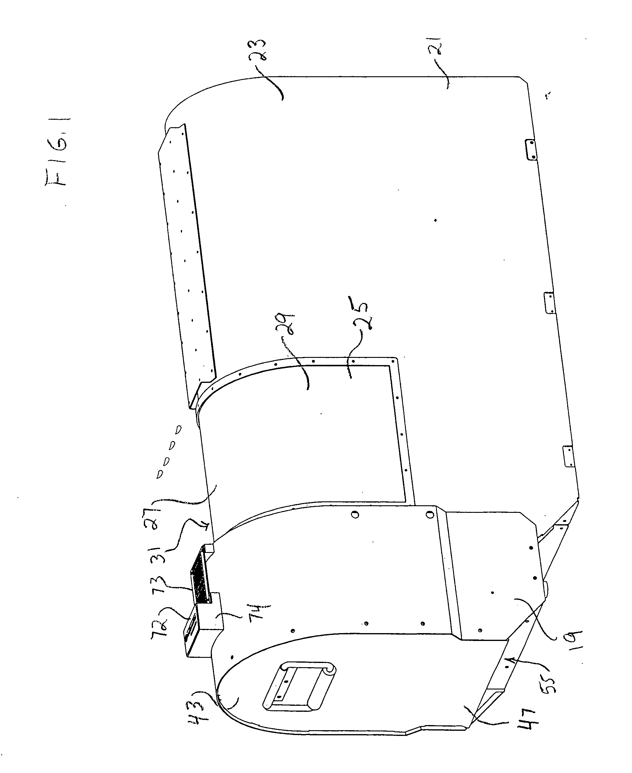
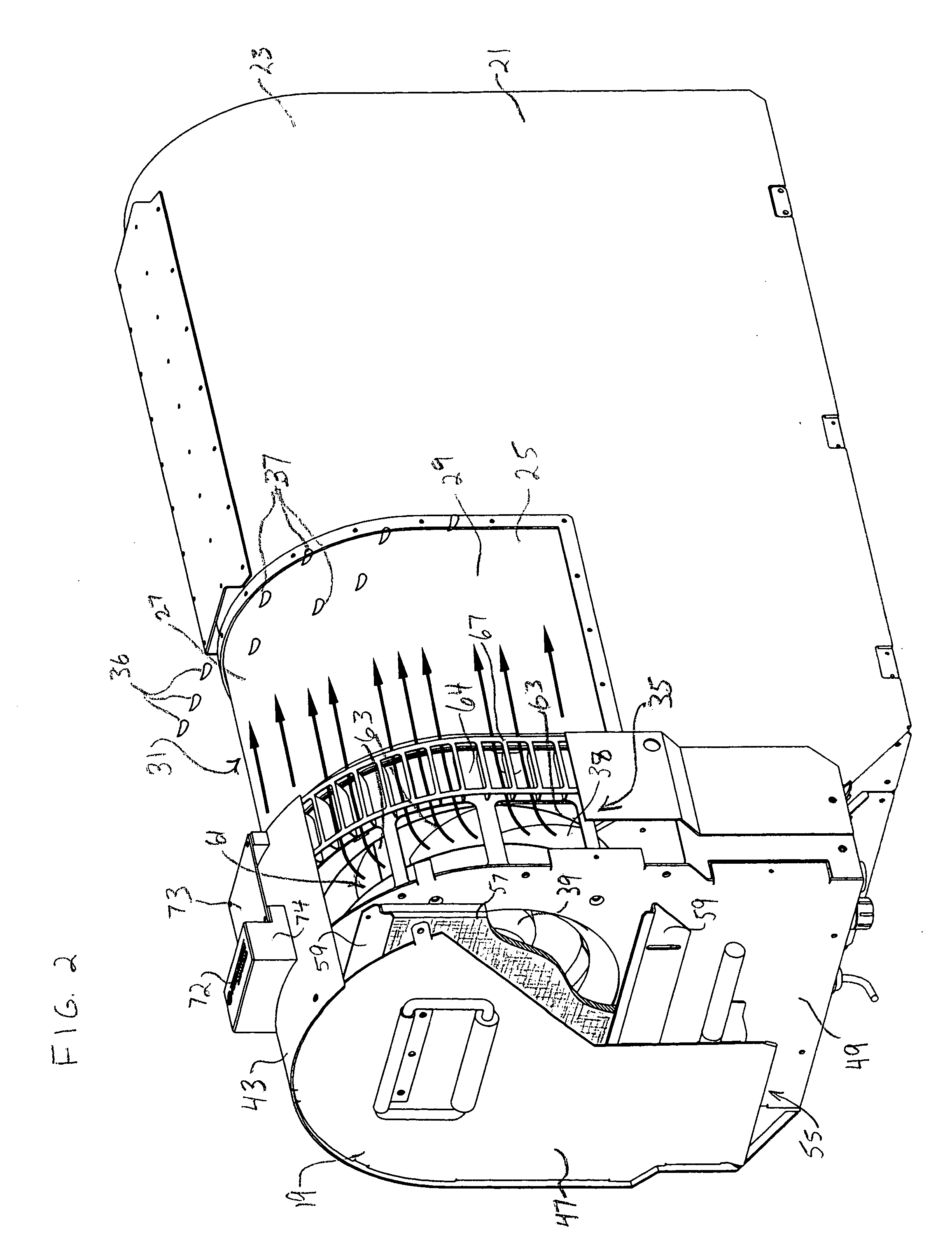
[0029] A first embodiment of an apparatus 19 for mitigating precipitation effects is shown in FIGS. 1 through 4 in association with microwave radiometer 21. As is known, microwave radiometer 21 includes an instrument housing 23 having an antenna system with a window 25 thereat. For use in a radiometer, window 25 (a radome having both upper surface 27 and lateral, or side, surfaces 29 and 31) is preferably formed from material which is nearly transparent to the broad band microwave signals of interest (Teflon, for example). Housing 23 protects the instrument and antennae (a radiometer with feed horn antennae of known configuration, for example) from the elements.

[0030] It should be appreciated that when the term “window” or “dielectric window” is utilized herein, any part of an antenna system in an instrument utilized to protect the actual antenna of the instrument in intended within the scope of such terminology, irrespective of type (dielectric windows, covers, protective films, f...


PUM

PropertyMeasurementUnit
forceaaaaaaaaaa
velocityaaaaaaaaaa
hydrophobicaaaaaaaaaa

Abstract

Apparatus and methods for mitigating precipitation effects realized at an antenna system of an instrument such as a microwave radiometer are disclosed. One embodiment of the apparatus includes a blower mechanism that enables instrument operation even during precipitation events (rain, snow, sleet, or excessive condensation) by causing a flow of air at relatively high velocity tangentially across the antenna system. The air flow is of sufficient force to disallow contact by hydrometeors with the antenna or antenna window of the system by redirecting the path of the falling hydrometeors in flight and/or to sweep hydrometeors reaching or formed at the window from the vicinity of the window. Other mechanisms for such precipitation effects mitigation are also disclosed.

Description

FIELD OF THE INVENTION [0001] This invention relates to instruments such as microwave radiometers having antennae systems, and, more particularly, relates to apparatus and methods for addressing the presence of moisture at such antennae systems. BACKGROUND OF THE INVENTION [0002] Heretofore, operation of microwave radiometers has generally severely degraded during precipitation events because of contamination of the radiometer antenna system by hydrometeors (precipitation particles in liquid, ice, or mixed or wetted phase). Hence, microwave radiometer measurements have not provided meaningful or useful data when made during precipitation events, primarily because liquid water and / or other precipitation products or contaminants on the dielectric window of the antenna system causes erroneously high measurement values. This inability to operate accurately during precipitation events has caused discontinuity of meteorological measurements and inhibited use of microwave radiometers for d...

Claims


Application Information

Patent Timeline
Patent Type & Authority Applications(United States)
IPC IPC(8): G01D11/24G01N7/00G01R27/04G01R27/32
CPCG01D11/24
Inventor WARE, RANDOLPHSOLHEIM, FREDRICKEXNER, MICHAEL L.
Owner RADIOMETRICS CORP
Why Eureka
Try Eureka