
High frequency oscillator using dielectric resonator

a dielectric resonator and high frequency technology, applied in the direction of oscillator generators, pulse automatic control, semiconductor/solid-state device details, etc., can solve the problems of complicated circuit configuration and low frequency stability, and achieve the effect of increasing the oscillation efficiency

Inactive Publication Date: 2005-08-25
NIHON DEMPA KOGYO CO LTD +1
View PDF8 Cites 7 Cited by
  • Summary
  • Abstract
  • Description
  • Claims
  • Application Information

AI Technical Summary

Benefits of technology

The present invention provides a second-harmonic oscillator that has high frequency stability without the need for injection synchronization. Additionally, the invention improves frequency stability and oscillation stability by using injection synchronization. The high frequency resonator includes a pair of amplifiers, a high frequency transmission line, and an electromagnetic coupling member that includes a dielectric resonator. The use of a dielectric resonator increases the Q-value in the oscillation system, resulting in higher frequency stability. The high frequency transmission line is preferably a microstrip line, and the electromagnetic coupling member can be made up of a dielectric resonator and a slot line. The slot line is electrically open, increasing the oscillation efficiency.

Problems solved by technology

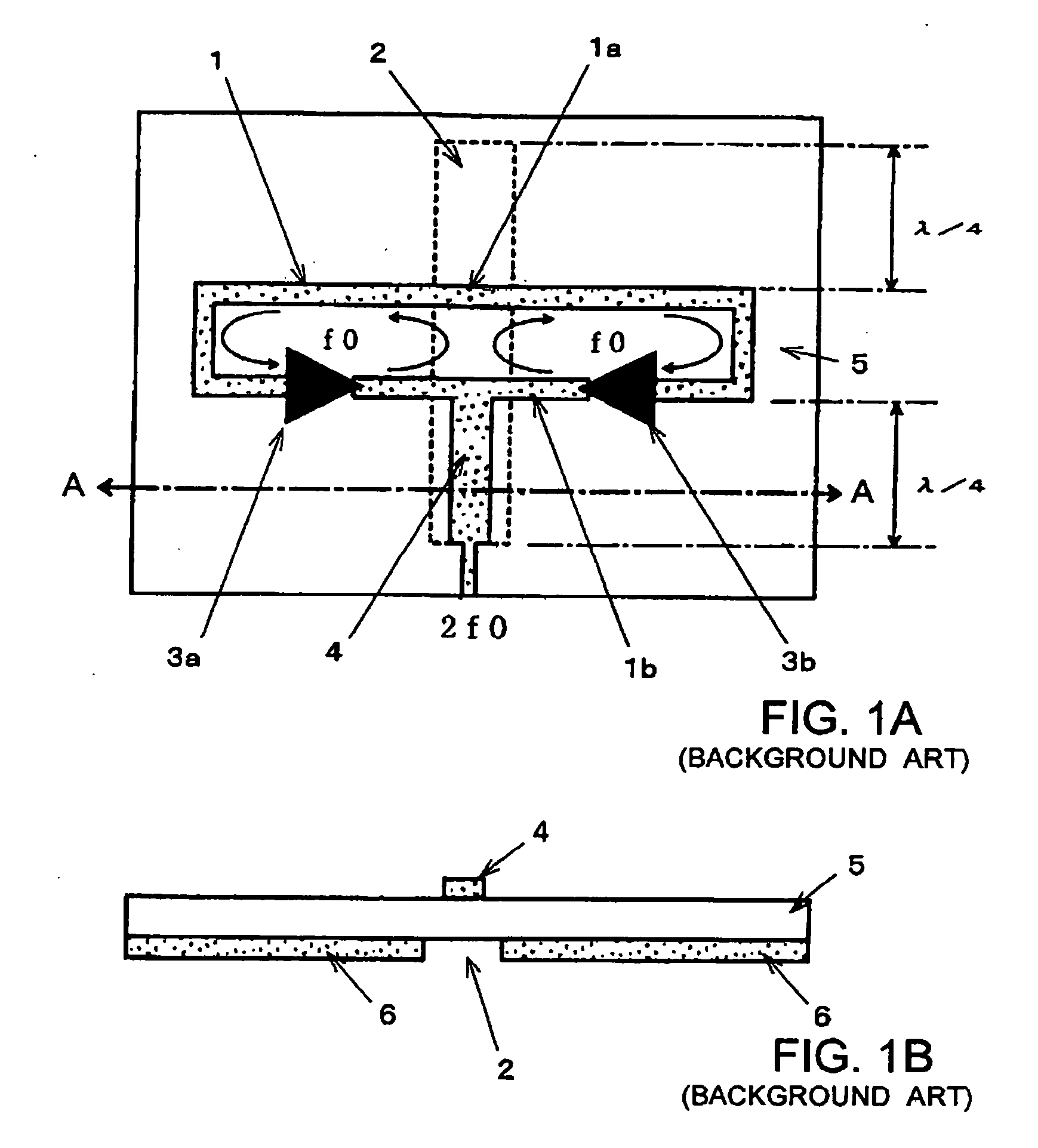
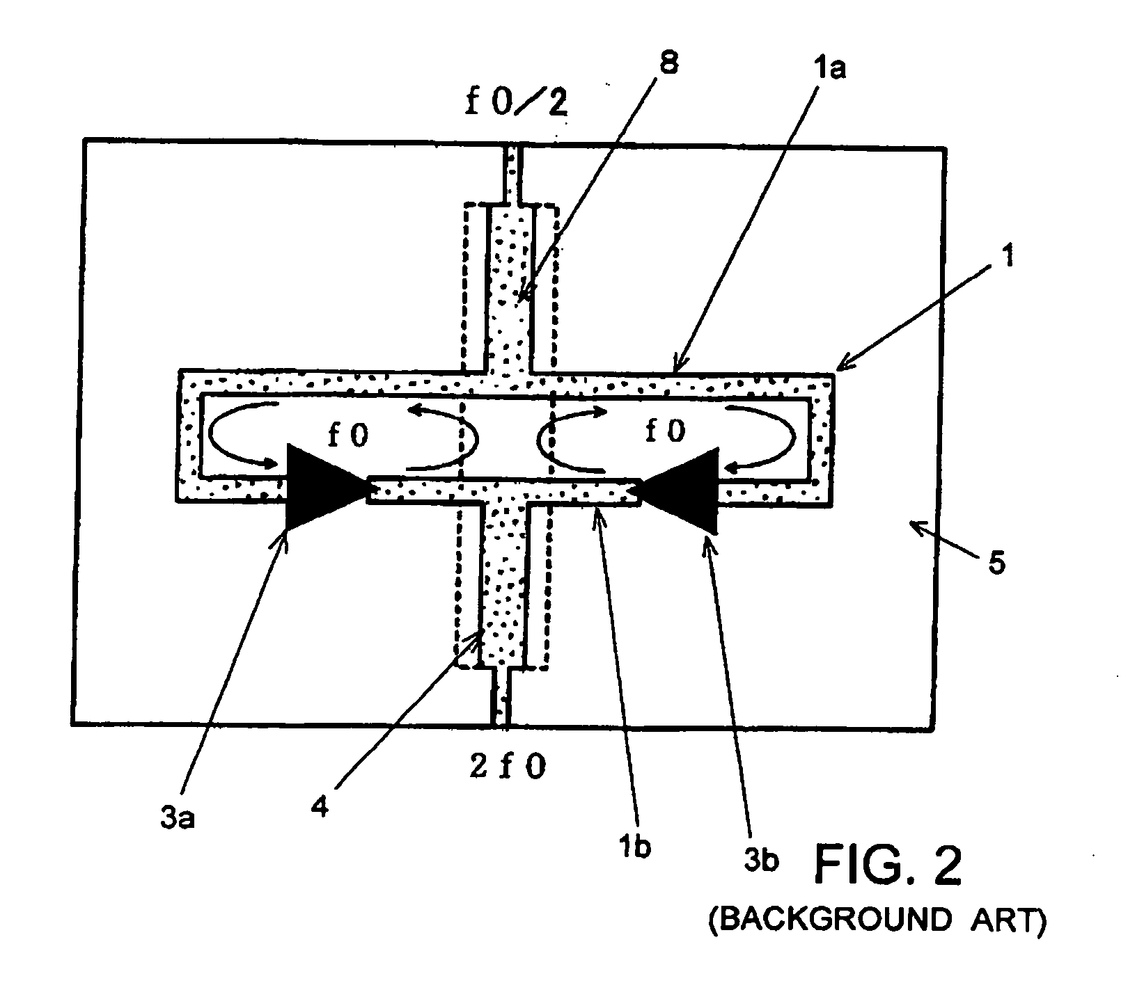
However, in the second-harmonic oscillator in the foregoing configuration, the oscillation frequency (fundamental frequency f0) of each oscillation system is determined depending on the length of the closed loop, but the Q-value is relatively small, causing a problem of a lower frequency stability.
However, the injection synchronization requires a synchronization signal source and the like, resulting in a complicated circuit configuration.

Method used


Image

  • High frequency oscillator using dielectric resonator
  • High frequency oscillator using dielectric resonator
  • High frequency oscillator using dielectric resonator

Examples


first embodiment

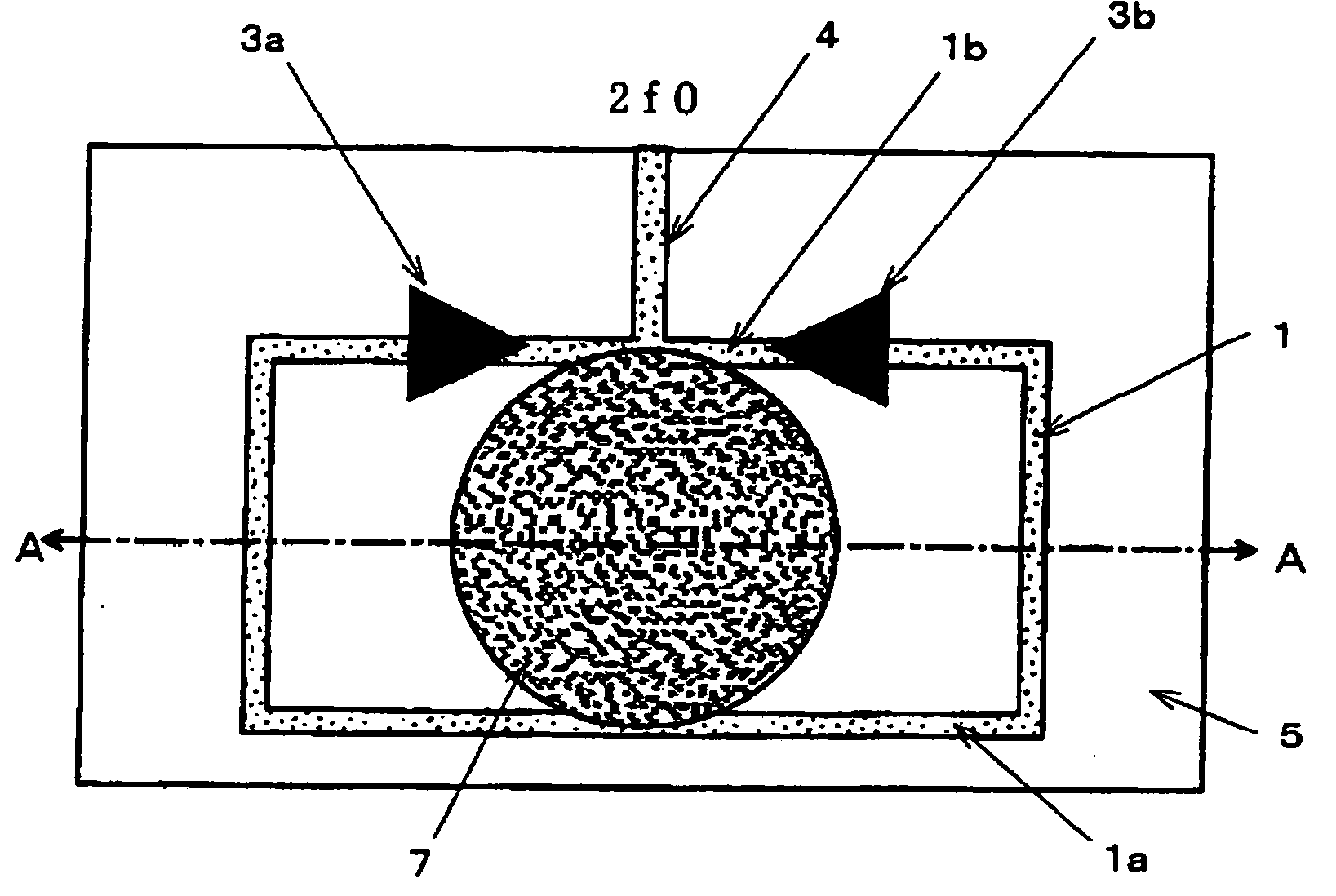
[0033] A second-harmonic oscillator according to the present invention illustrated in FIGS. 3A and 3B comprises dielectric resonator 7 instead of the slot line in the oscillator illustrated in FIGS. 1A and 1B. In FIGS. 3A and 3B, components identical to those in FIGS. 1A and 1B are designated the same reference numerals, and repeated description thereon is simplified.

[0034] The second-harmonic oscillator illustrated in FIGS. 3A and 3B, like the one illustrated in FIGS. 1A and 1B, comprises a pair of amplifiers 3a, 3b for oscillation; microstrip line 1 as a high frequency transmission line; output line 4 in microstrip line structure for an oscillation output; and dielectric substrate 5. Amplifiers 3a, 3b, microstrip line 1, and output line 4 are all disposed on one principal surface of dielectric substrate 5, while ground conductor 6 is disposed over the entirety of the other principal surface of dielectric substrate 5. Microstrip line 1 is routed in a rectangular shape such that a c...

second embodiment

[0042] Alternatively, in the second embodiment, one of slot lines 2a, 2b may be removed, and instead, dielectric resonator 7 may be electromagnetically coupled directly to microstrip line 1. FIGS. 5A and 5B illustrate such a double-wave oscillator. In the illustrated second-harmonics oscillator, slot line 2a remains coupled to the upper side section of microstrip line 1, whereas slot line 2b, which would otherwise would be coupled to the lower side section, has been removed. Instead, dielectric resonator 7 overlies microstrip line 1 in contact therewith for electromagnetic coupling to microstrip line 1 near the midpoint of the lower side section of microstrip line 1. Such a second-harmonic oscillator can provide similar advantages to those of the oscillator illustrated in FIGS. 4A and 4B.

[0043] Next, description will be made on a second-harmonic oscillator according to a third embodiment of the present invention. In the first and second embodiments, microstrip line 1 has been routed...

third embodiment

[0045] Likewise, in the second-harmonic oscillator the fundamental wave (f0) component is not delivered from output line 4 but the second-harmonic (2f0) component is delivered, as is the case with the respective oscillators of the aforementioned embodiments.


PUM


Abstract

A second-harmonic oscillator based on push-push oscillation has a pair of amplifiers for oscillation, a high frequency transmission line for connecting inputs of the pair of amplifiers to each other and connecting outputs of the pair of amplifiers to each other, and an electromagnetic coupling member disposed between the inputs and outputs of the pair of amplifiers such that it is electromagnetically coupled to the high frequency transmission line. The electromagnetic coupling member includes at least a dielectric resonator. The pair of amplifiers, high frequency transmission line, and electromagnetic coupling member form two oscillation loops which oscillate in opposite phases to each other with respect to a fundamental wave of oscillation for generating a second harmonic of the fundamental wave.

Description

BACKGROUND OF THE INVENTION [0001] 1. Field of the Invention [0002] The present invention relates to a high frequency oscillator for use in a millimeter-wave band, a microwave band and the like, and more particularly, to a high frequency oscillator which can generate an output at a frequency twice as high as a fundamental wave of an oscillation frequency through so-called push-push oscillation. [0003] 2. Description of the Related Art [0004] A push-push oscillation based oscillator is known as suitable for generating oscillation signals in a millimeter-wave band and a microwave band. The oscillator based on push-push oscillation employs a pair of oscillation circuits which operate at the same fundamental frequency but in opposite phases to each other, and combines the outputs from these oscillation circuits to cancel out the fundamental wave components and extract even-order harmonic components to the outside. Such push-push oscillators are used in a variety of applications because ...

Claims


Application Information

Patent Timeline
Patent Type & Authority Applications(United States)
IPC IPC(8): H01P5/08H01P7/10H03B5/18H03B19/18H03L7/24
CPCH03B5/1894
Inventor AIKAWA, MASAYOSHITANAKA, TAKAYUKIASAMURA, FUMIOOITA, TAKEO
Owner NIHON DEMPA KOGYO CO LTD
Learn More