Projection type image display apparatus

a projection type and image display technology, applied in the field of projection devices, can solve the problems of black image contrast deterioration, performance decline, and unsatisfactory effect of quarter-wave plates, and achieve the effects of high contrast, high resolution, and satisfactory image quality performances

Inactive Publication Date: 2005-08-25
HITACHI LTD
View PDF8 Cites 11 Cited by
  • Summary
  • Abstract
  • Description
  • Claims
  • Application Information

AI Technical Summary

Benefits of technology

[0007] The present invention has been made in view of the above problems and provides a light, compact reflection type image display apparatus which uses reflection image display devices to deliver satisfactory image quality performances such as brightness, high contrast, and high resolution.

Problems solved by technology

For this reason, rays which are not parallel to the main incidence plane may cause light leakage, resulting in black image contrast deterioration.
However, in the case that a PBS prism is used as a polarizer / analyzer for a reflection type liquid crystal panel as mentioned above, even when a quarter-wave plate is disposed just before the panel in order to prevent contrast deterioration, the effect of the quarter-wave plate is not satisfactory.
As the difference of the incident light wavelength from the design center wavelength increases or the incidence angle increases, the performance of the wave plate decreases, so light leakage cannot be prevented completely and contrast deterioration will occur.
Even when a polarizing plate is disposed between the PBS prism and the projection lens for the purpose of preventing leak light from being projected on the screen, it is impossible to prevent light leakage completely because the leak light includes rays polarized in the same direction as the direction of the polarizing plate transmission axis.
Besides, the use of the PBS prism is disadvantageous from the view point of weight.
Furthermore, when the PBS prism uses a glass material with a low photoelastic coefficient to avoid birefringence which might cause contrast deterioration, it may be relatively heavy because of the relatively large specific gravity of the glass material, and costly because the material is not widely available on the market.

Method used


Image

  • Projection type image display apparatus
  • Projection type image display apparatus
  • Projection type image display apparatus

Examples


second embodiment

[0038] Next, the invention will be described referring to FIG. 3.

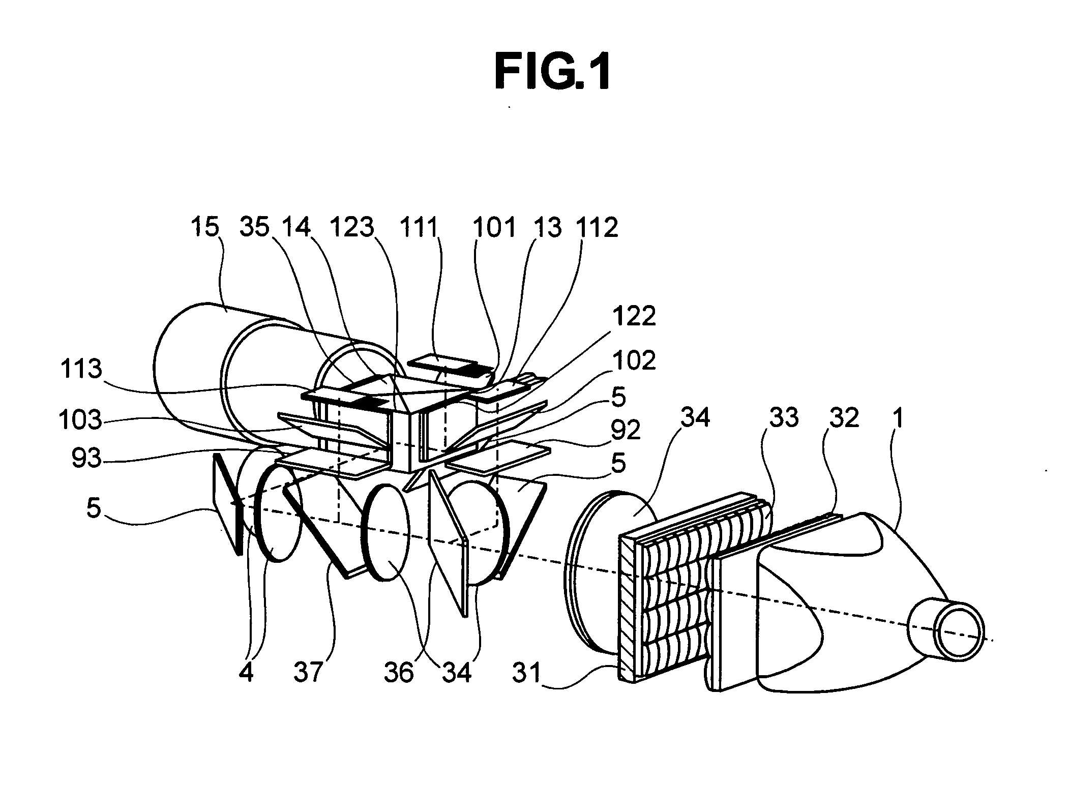
[0039] The portion from the lamp unit 1 to the collimator lens 34 is the same as in the embodiment shown in FIG. 1 except that the first lens array and the second lens array have horizontally long cells and a polarization converter 31 is disposed in a way to match vertical pitches and the light path is bent approximately 90 degrees by the reflection mirror 5.

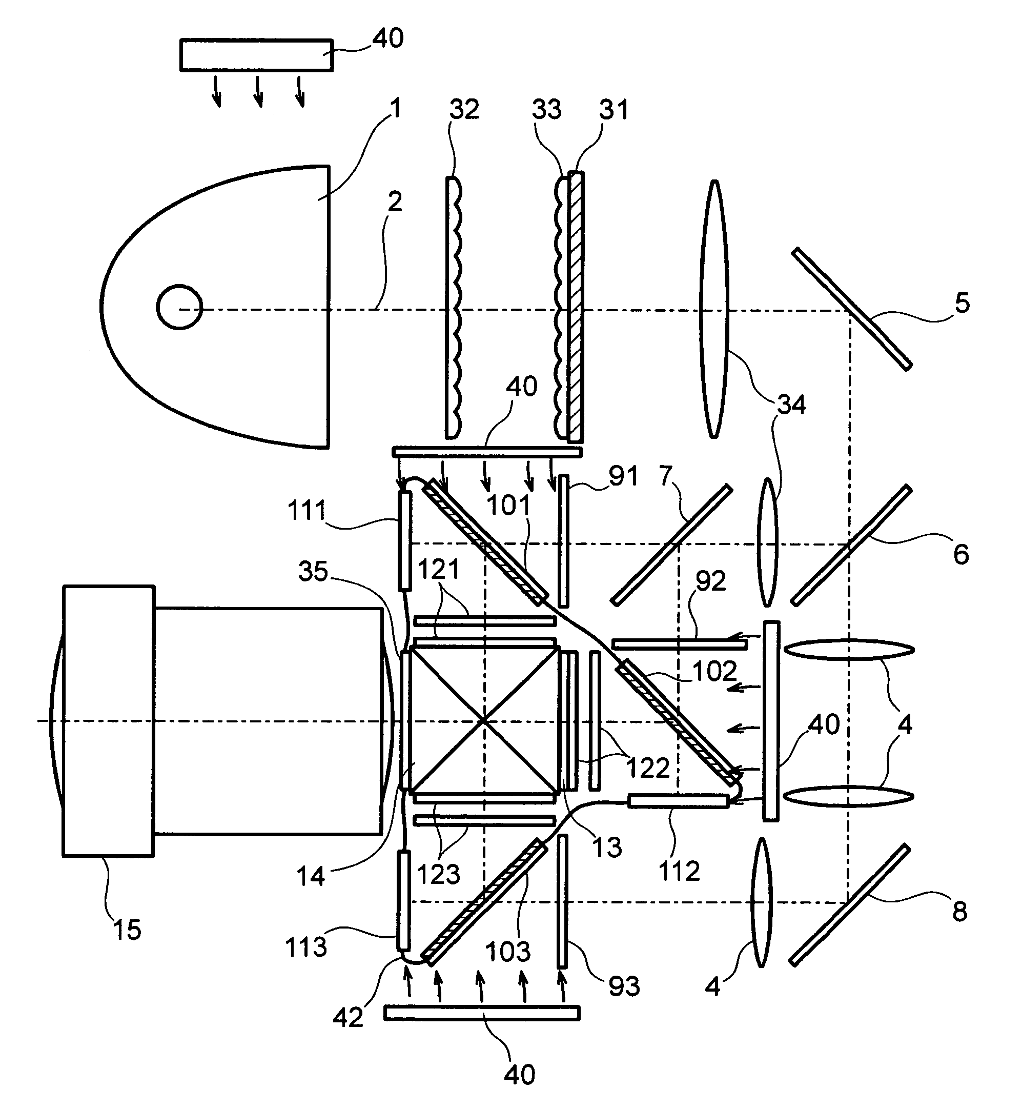
[0040] Light is separated into R (red), G (green), and B (blue) light by dichroic mirrors 6 and 7. Then, B light rays are bent 90 degrees by a B-reflection mirror 17. R, G, and B light respectively pass through R, G, and B light auxiliary polarizers 91, 92, 93, then through R, G, and B light reflection polarizing plates 101, 102, 103 and respectively reach R, G, and B light reflection liquid crystal panels 111, 112, 113. The rays reflected by the R, G, and B light reflection liquid crystal panels are reflected and bent 90 degrees by the R, G, and B light reflectio...

third embodiment

[0049]FIG. 4 shows the present invention. The structure is the same as that of the embodiment illustrated in FIG. 3 except the following points. The reflection polarizing plates 10, reflection liquid crystal panels 11 and auxiliary analyzers 9 are located on the surface of the hermetically sealed chassis 42 which borders on the outside. Because the hermetically sealed chassis 42 are dustproof, they prevent dust adhesion on the reflection polarizing plates 10, reflection liquid crystal panels 11, etc., so that on-screen image missing or image quality deterioration may not occur. The use of optical components such as the reflection polarizing plates 10 and auxiliary analyzers 9 as boundaries assures air tightness without interfering with the light paths. Hermetic seals are placed between the optical components and the chassis 42 to assure air tightness. A cooling fan cools the auxiliary analyzers. Only the rear sides of the reflection liquid crystal panels 11 are exposed to the outsid...

fourth embodiment

[0050]FIG. 5 shows the present invention. The structure is the same as that of the embodiment illustrated in FIG. 3 except the following points. A color separation system separates light into R, G and B light, which pass through the auxiliary analyzers 91, 92, and 93 and through the reflection polarizing plates 10 and reach the reflection liquid crystal panels 11. The image light modulated and reflected by the reflection liquid crystal panels 11 is reflected by the reflection polarizing plates 10 before entering a color combining prism 14. A hermetically sealed chassis 42 houses the reflection polarizing plates 10, reflection liquid crystal panels 11, cross dichroic prism 14 and auxiliary analyzers 9 and has auxiliary polarizers 9 on its boundaries. A cooling fan cools the auxiliary analyzers 9.

[0051] Alternatively, the reflection polarizing plates 10, reflection liquid crystal panels 11, cross dichroic prism 14 and quarter-wave plates 9 may be located on the boundaries of the herme...


PUM

PropertyMeasurementUnit
aspect ratioaaaaaaaaaa
angleaaaaaaaaaa
angleaaaaaaaaaa

Abstract

A compact, light projection type image display apparatus based on reflection image display devices which provide high brightness without contrast deterioration caused by light leakage associated with black image display. The apparatus uses, as polarizers / analyzers for reflection image display devices, reflection polarizing plates which function as polarizing plates by their grating function only in a specific direction. In each light path, the reflection polarizing plate is located just before / after the reflection image display device.

Description

BACKGROUND OF THE INVENTION [0001] The present invention relates to a projector which projects an image on a screen using reflection liquid crystal panels such as a reflection liquid crystal projector, a projection type image display apparatus such as a reflection liquid crystal rear projector, and a projection type image display apparatus optical unit. [0002] An optical unit for a reflection liquid crystal projector which uses reflection liquid crystal panels is explained next. Non-polarized light coming from a light source is linearly polarized by a polarization converter and cast on a polarizer. The unwanted polarized component is removed from the light by the polarizer before it reaches a reflection liquid crystal panel. The light is modulated by the reflection liquid crystal panel so that its polarization state is changed on a pixel-by-pixel basis according to image signal. Then, it reaches an analyzer. The quantity of light which is transmitted or reflected by the analyzer is ...

Claims


Application Information

Patent Timeline
Patent Type & Authority Applications(United States)
IPC IPC(8): G02B27/28G02B5/30G02F1/13G02F1/1335G03B21/00G03B21/16H04N9/31
CPCG03B21/14H04N9/3197H04N9/3167H04N9/3105G03B21/16G03B21/2073G03B33/12G02B27/28
Inventor IMAHASE, TAROOUCHI, SATOSHINAKASHIMA, TSUTOMU
Owner HITACHI LTD
Why Eureka
Try Eureka