
Thermally compensated differential

a differential and temperature compensation technology, applied in the direction of gearing, gearing details, hoisting equipment, etc., can solve the problems of uneven or premature wear, mechanism rotation, more loosening of bearings, etc., to achieve accurate bearing positioning, high reliability, and convenient use

Active Publication Date: 2005-08-25
THE TIMKEN CO
View PDF12 Cites 6 Cited by
  • Summary
  • Abstract
  • Description
  • Claims
  • Application Information

AI Technical Summary

Benefits of technology

[0008] Accordingly, it will be recognized that an object of the present invention is to provide a thermally compensated differential that is capable of compensating for any thermal expansion that may occur due to dissimilar materials.
[0009] A further object of the present invention is to provide a thermally compensated differential that can be easily employed with highly reliable results.
[0010] Another object of the present invention is to provide a thermally compensated differential having adjustable spacers that can be adjusted to accurately set the bearings that are mounted indirectly.

Problems solved by technology

Additionally, the diameter growth of the housing bores containing the bearings will expand to a greater amount causing even more loosening of the bearings.
If this occurs then the antifriction bearings found in the differential gear mechanism may become loose which can cause the mechanism to rotate improperly, wear unevenly or prematurely, fail, or produce noise.
However, it has proven very difficult to set or assemble these bearings when their apices are orientated inwardly due to the required press fit on the differential case.

Method used


Image

  • Thermally compensated differential
  • Thermally compensated differential
  • Thermally compensated differential

Examples


Embodiment Construction

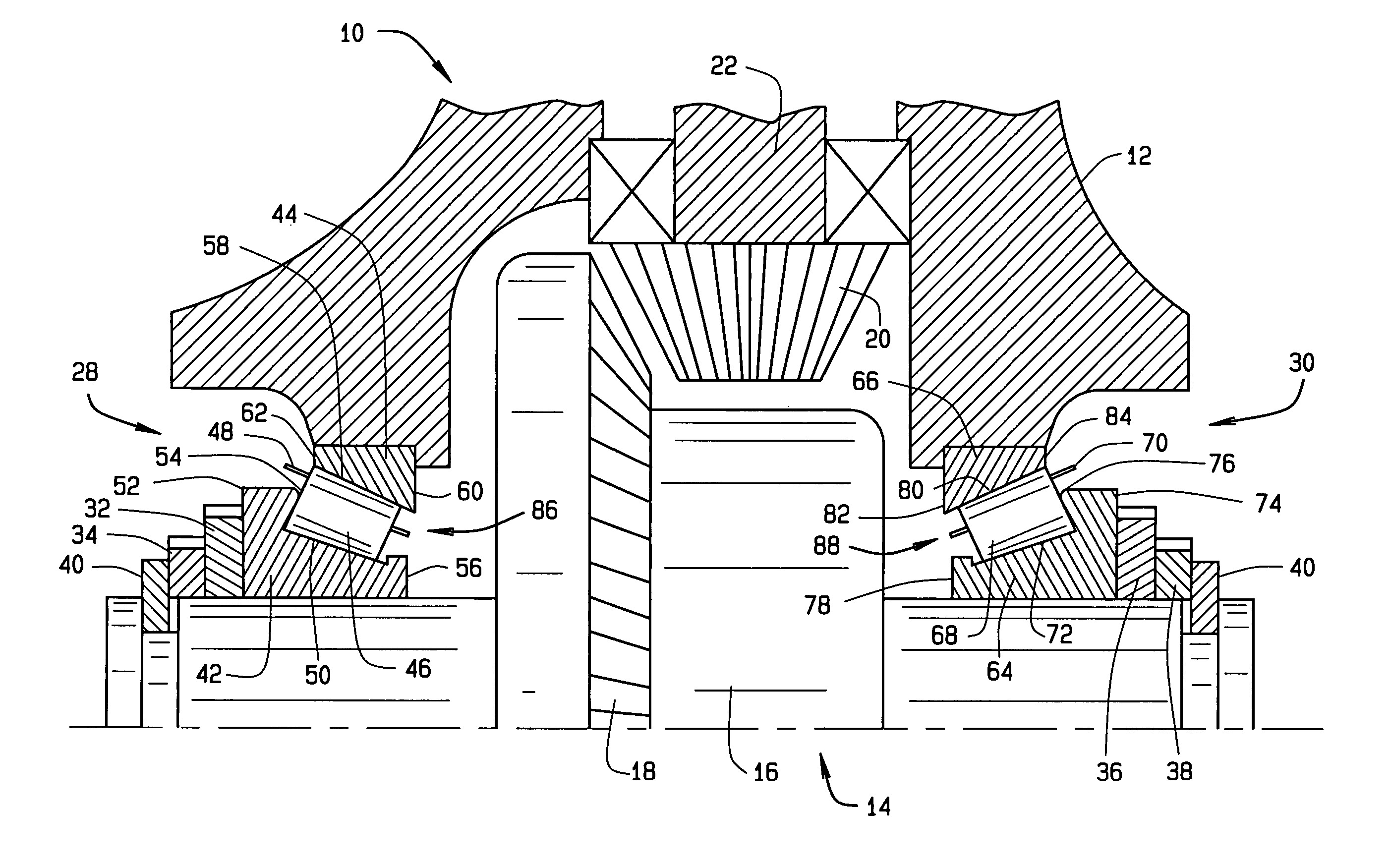
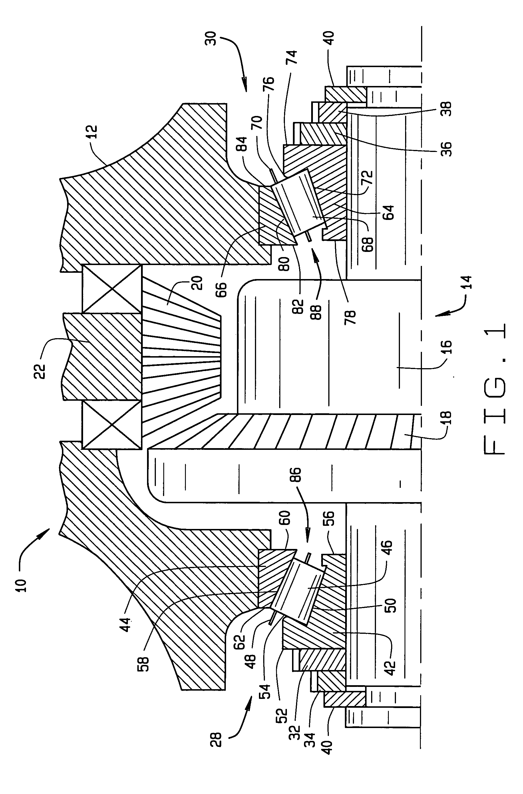
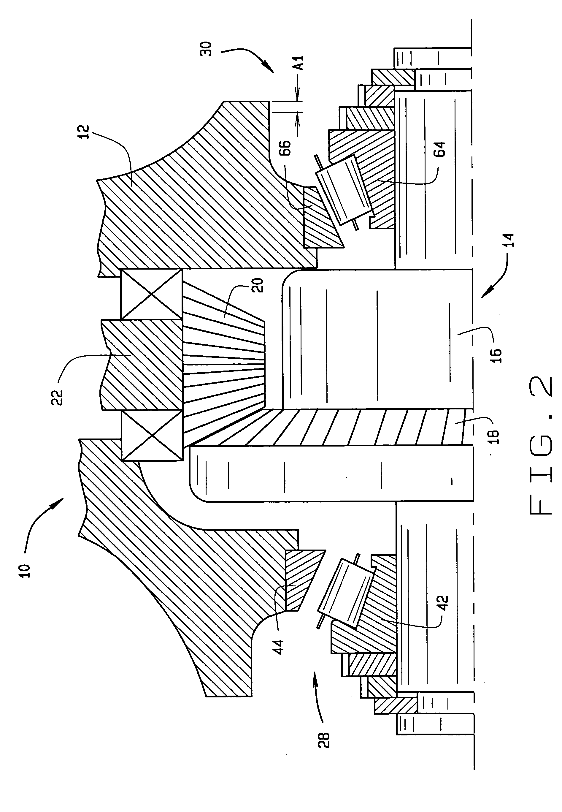
[0022] Referring now to the drawings and in particular to FIG. 1, a thermally compensated differential 10 constructed according to the present invention is shown. The thermally compensated differential 10 has an axle housing 12 that may be constructed from aluminum. The housing 12 is used to cover or house a differential gear mechanism 14. The mechanism 14 includes a differential case 16 that is constructed of a metal different from that which the housing 12 is constructed, a ring gear 18 that meshes with a beveled drive pinion 20, and a pinion shaft 22. The differential 10 is a specialized form of a gear reduction unit for automobile axles. A pair of roller bearings supports the pinion 20 and the pinion shaft 22. The housing 12 and the case 16 are supported by a first or left roller bearing assembly 28 and a second or right roller bearing assembly 30. A first pair of adjustable disks or spacers 32 and 34 are associated with the first roller bearing assembly 28 and a second pair of ...


PUM


Abstract

A thermally compensated differential comprises a housing, a pinion gear mounted into the housing, a differential case carrying a ring gear with the case being supported by a first roller bearing and a second roller bearing with the bearings being mounted indirectly, and the first and second roller bearings being contacted by adjustable spacers.

Description

CROSS-REFERENCE TO RELATED APPLICATIONS [0001] This application claims priority on U.S. Provisional patent application Ser. No. 60 / 547,118, entitled THERMALLY COMPENSATED DIFFERENTIAL that was filed on Feb. 24, 2004.STATEMENT REGARDING FEDERALLY SPONSORED RESEARCH OR DEVELOPMENT [0002] Not applicable. BACKGROUND OF THE INVENTION [0003] This invention relates in general to opposed antifriction bearings and, more particularly, to an apparatus or an installation method for setting antifriction bearings between a housing and a differential carrier or case or a gear reduction unit constructed of dissimilar materials or metals. [0004] Differential gear mechanisms transfer rotational torque from an input shaft member to a pair of output shaft members. One typical application of a differential gear mechanism is that of an automobile with the pair of output shaft members having the rear wheels attached thereto. A torque generating device such as a gasoline engine or an electric motor is typi...

Claims


Application Information

Patent Timeline
IPC IPC(8): F16C25/06F16H48/06F16H48/08F16H48/40F16H57/02F16H57/021F16H57/022F16H57/037
CPCF16C25/06F16H48/06F16H48/08F16H57/021Y10T74/19623F16H2048/405F16H2057/0221Y10T74/19693F16H57/037F16C2361/61
Inventor JOKI, MARK A.ROSS, SHARON E.
Owner THE TIMKEN CO
Learn More