Direct current cutoff switch

a cutoff switch and current technology, applied in the direction of relays, snap-action arrangements, contacts, etc., can solve the problems of high surge voltage, circuit short circuit, and inability to solve contact meltdown problems, so as to prevent contacts from fusing and prolong use

Inactive Publication Date: 2005-09-01
UCHIYA THERMOSTAT
View PDF8 Cites 5 Cited by
  • Summary
  • Abstract
  • Description
  • Claims
  • Application Information

AI Technical Summary

Benefits of technology

[0027] As described above, according to the present invention, since a PTC whose voltage / current characteristic and temperature characteristic are especially set is parallel connected to the contact circuit of a switch which is opened in the first place, of switches opened before and after, a closed circuit is formed and surge voltage is difficult to occur even if high-voltage current is cut off by opening the contacts of the first switch. Then, the PTC passes through the minimum resistance area to almost cut off current and further to complete the current cutoff operation by a contact opened later. Thus, direct current with 30V to 50V or higher voltage of 130V to 310V can be rapidly and certainly cut off without setting a distance between contacts to be opened wide. Accordingly, the miniaturization of a switching mechanism can be realized, the recent miniaturization of electronic equipment can be easily realized and its usage can be extended, which is convenient.
[0028] Since surge voltage is difficult to occur, no arc occurs between contacts. Therefore, the contacts can be prevented from fusing. Accordingly, a highly-reliable long-life high-voltage direct current cutoff switch can be provided.

Problems solved by technology

This is because high surge voltage occurs if such high voltage / large current is cut off.
As a result, the circuit is short-circuited by melting down the contacts and generating fusion between the contacts.
Alternatively, even if the contacts are maintained open, a dielectric member around the contacts often melts, produces smoke or fire by heat, which is a problem.
Therefore, the problem of contact meltdown cannot be solved.
However, the value of a resistor sufficient to reduce current so as to dissolve or suppress sparks is very low.
If such a low resistance value is connected even after the contacts are opened, the accumulated amount of leak current becomes too large to neglect and uneconomical.
However, any of these devices is used to protect circuits driven by the above-mentioned voltage in use from abnormal surge voltage by absorbing high surge voltage at the time of emergency, different from voltage in use, and is not originally used to absorb surge voltage almost the same as voltage used at the time of the opening / closing of a switch.
Therefore, even if a surge voltage absorbing device which is used to absorb high voltage at the time of emergency, different from the voltage in use, and has a characteristic that a safety margin is set between voltage in use and surge restricting voltage, is inserted between the contacts of a normal switch, the surge voltage absorbing device does not operate, that is, cannot fulfill a function to absorb surge voltage, since surge voltage at the time of the opening / closing of the switch is almost the same as the voltage in use.
Since generally a surge voltage absorbing device has the nature of absorbing surge voltage by reducing its resistance value by self-heating, using higher voltage, if far higher excessive voltage is applied, in the worst case, thermal runaway occurs and self-destruction is caused.
Therefore, from this point of view too, the conventional surge voltage absorbing device has not been consideration to absorb surge voltage far higher than power supply voltage generated in the contacts of a switch.

Method used


Image

  • Direct current cutoff switch
  • Direct current cutoff switch
  • Direct current cutoff switch

Examples


Embodiment Construction

[0101] The preferred embodiments of the present invention are described below with reference to the drawings. The direct current cutoff switch embeds a PTC with a special characteristic, which is described later.

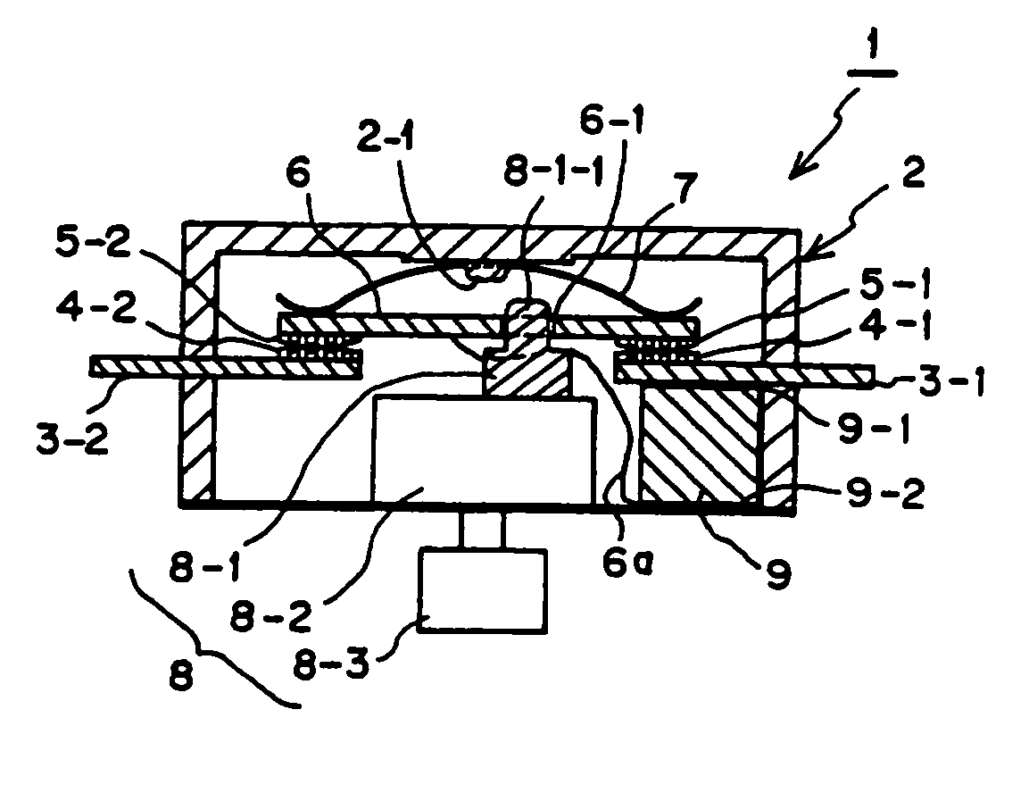
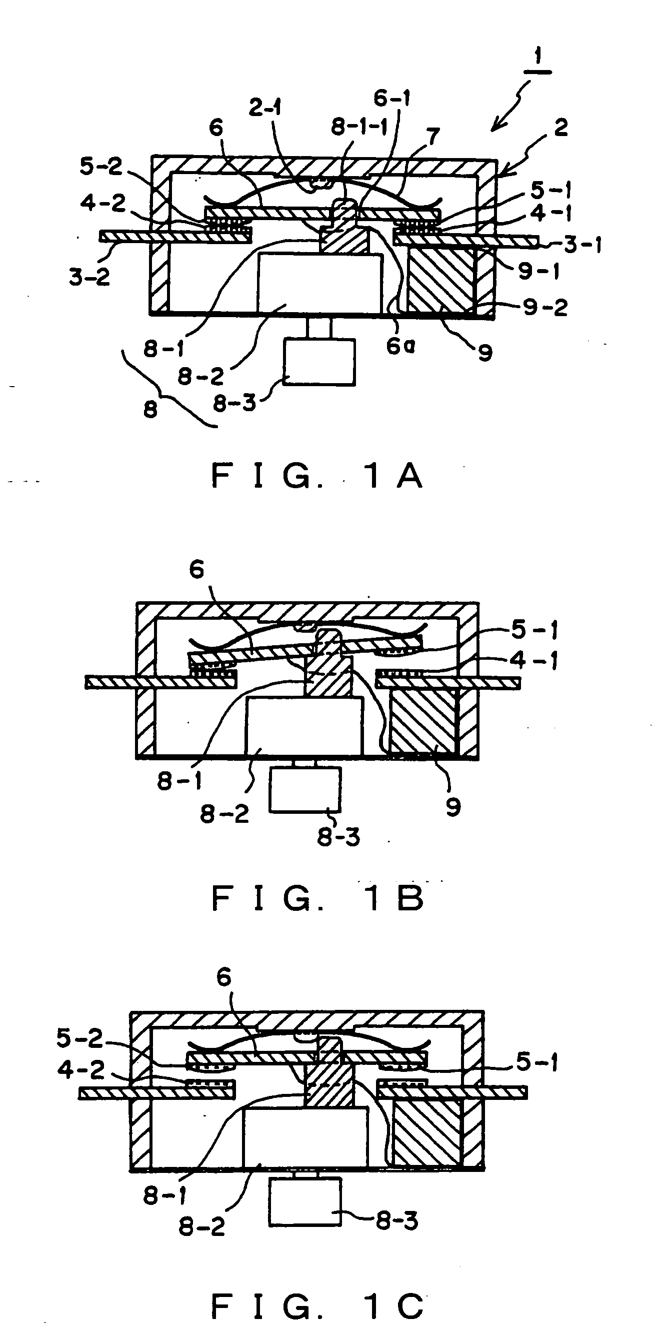
[0102]FIG. 1A is a section view showing the structure of a push-button type manually-operated switch as a direct current cutoff switch in the first preferred embodiment. FIGS. 1B and 1C show the operating states of this manually-operated switch together with FIG. 1A.

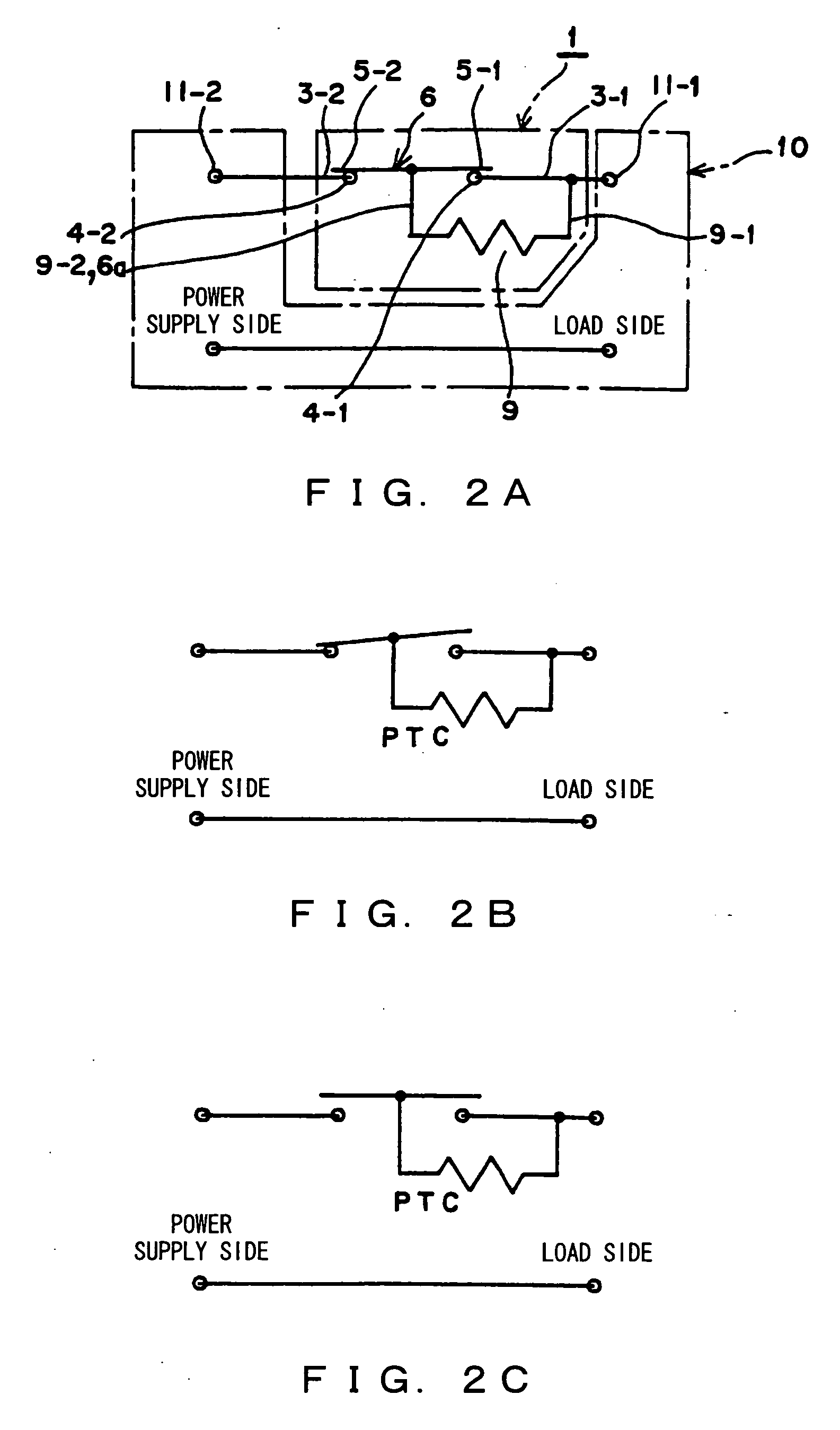
[0103]FIGS. 2A, 2B and 2C typically show the circuit configurations of the manually operated switch, corresponding to FIGS. 1A, 1B and 1C as well as the configuration of an external circuit.

[0104] The manually operated switch 1 shown in FIGS. 1A and 2A comprises a first fixed contact 4-1 which is disposed and formed in a prescribed position (in FIG. 1A, right against the center) of a housing 2 shown in FIG. 1A and is connected to a connecting section 3-1 to be connected to the connecting terminal 11-1 of an ex...


PUM


Abstract

In a manually operated switch for cutting off direct current, a PTC 9 as a non-linear resistor is parallel connected to a contact circuit composed of a first fixed contact 5-1 and a first movable contact 4-1, via a connecting unit 3-1, a top electrode 9-1, a bottom electrode 9-2, a connecting wire 6a and a movable unit 6. Firstly, the first fixed contact 5-1 and the first movable contact 4-1 are opened. However, since the PTC 9 is parallel connected and the contact circuit forms a closed circuit, surge voltage is difficult to occur, and cutoff current flows in the PTC 9. After peak current passes by the decrease of a resistance value due to the instantaneous heating of the PTC 9, voltage returns to power supply voltage by the increase of the resistance value of the PTC 9, and then the fixed contact 5-2 and the second movable contact 4-2 are opened. Accordingly, current is completely cut off.

Description

TECHNICAL FIELD [0001] The present invention relates to a direct current cutoff switch, more particularly, to a direct current cutoff switch for preventing contacts from melting down and reducing its damage by getting rid of or reducing the occurrence time of the contact-opening arc of a high-voltage current circuit, and completely cutting off high-voltage direct current. BACKGROUND ART [0002] There is conventionally a switch used for the opening / closing of a direct current circuit in the electrical equipment of automobiles, electronic products driven by a charging battery or the like. Power supply voltage for driving the electrical equipment of the conventional automobile in which such a switch is used is mainly DC 12V or DC 24V, and power supply voltage for portable electronic equipment using a charging battery is also mainly DC12V. [0003] Even motor-driven tools required to output high power can be sufficiently driven by DC 18V or 24V, and the conventional switch has been used as...

Claims


Application Information

Patent Timeline
Patent Type & Authority Applications(United States)
IPC IPC(8): H01H1/20H01H13/02H01H9/42H01H13/00H01H37/52H01H37/54H01H50/02H01H50/32H01H50/38H01H50/54H01H51/00
CPCH01H1/2016H01H9/42H01H13/00H01H37/54H01H2037/5481H01H50/326H01H50/54H01H51/00H01H50/021
Inventor TAKEDA, HIDEAKI
Owner UCHIYA THERMOSTAT
Why Eureka
Try Eureka