Mass-flow sensor heating element protection method and apparatus

Active Publication Date: 2005-09-01
VOLVO LASTVAGNAR AB +1
View PDF8 Cites 34 Cited by
  • Summary
  • Abstract
  • Description
  • Claims
  • Application Information

AI Technical Summary

Benefits of technology

[0018] In several embodiments of the invention, a ceramic heating element may be protected from thermal shock or over-heating during cold start and other conditions where condensed water/ice could be pre

Problems solved by technology

Controlling the amounts of emissions produced by an internal combustion engine, then, becomes an issue of balancing combustion efficiency against raising combustion temperatures high enough to produce oxides of nitrogen.
If too much exhaust gas is readmitted to the intake manifold, combustion will be impaired.
A heating element in an EGR conduit from the exhaust manifold to the intake manifold will be exposed to extremes of temperature.
Furthermore, the difference in temperature between the cold intake air and the hot exhaust gases may be dramatic.
If the switch from cold intake air to hot exhaust gases occurs quickly enough, the thermal stresses may amount to thermal shock in the heating element.
If the thermal shock is severe enough, the ceramic heating element may crack.
Condensation from the intake air or from cold exhaust gases left in the EGR conduit may enter these cracks and freeze while the engine is shut down.
Since water expands when it freezes, condensate freezing inside cracks

Method used


Image

  • Mass-flow sensor heating element protection method and apparatus
  • Mass-flow sensor heating element protection method and apparatus
  • Mass-flow sensor heating element protection method and apparatus

Examples


first embodiment

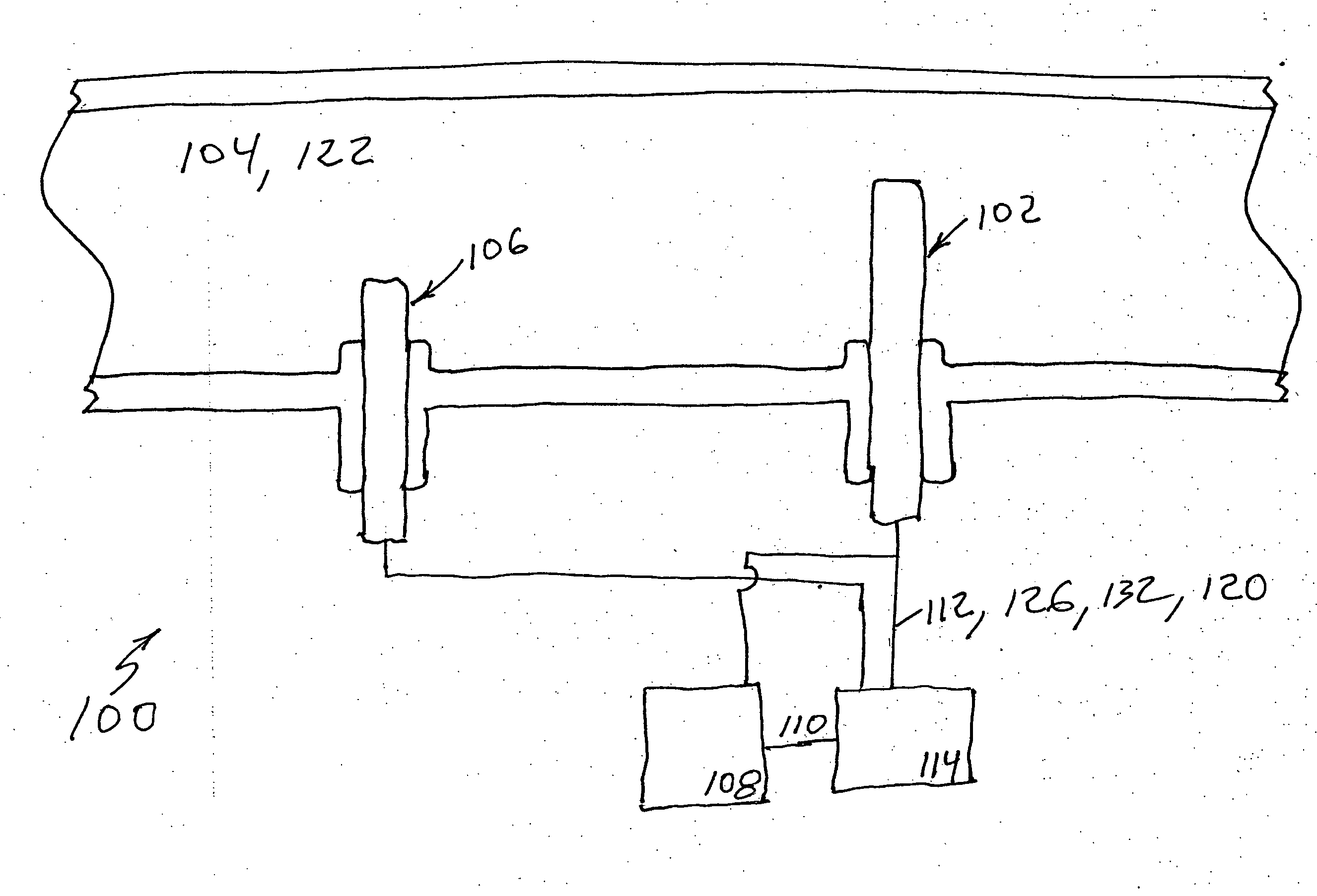
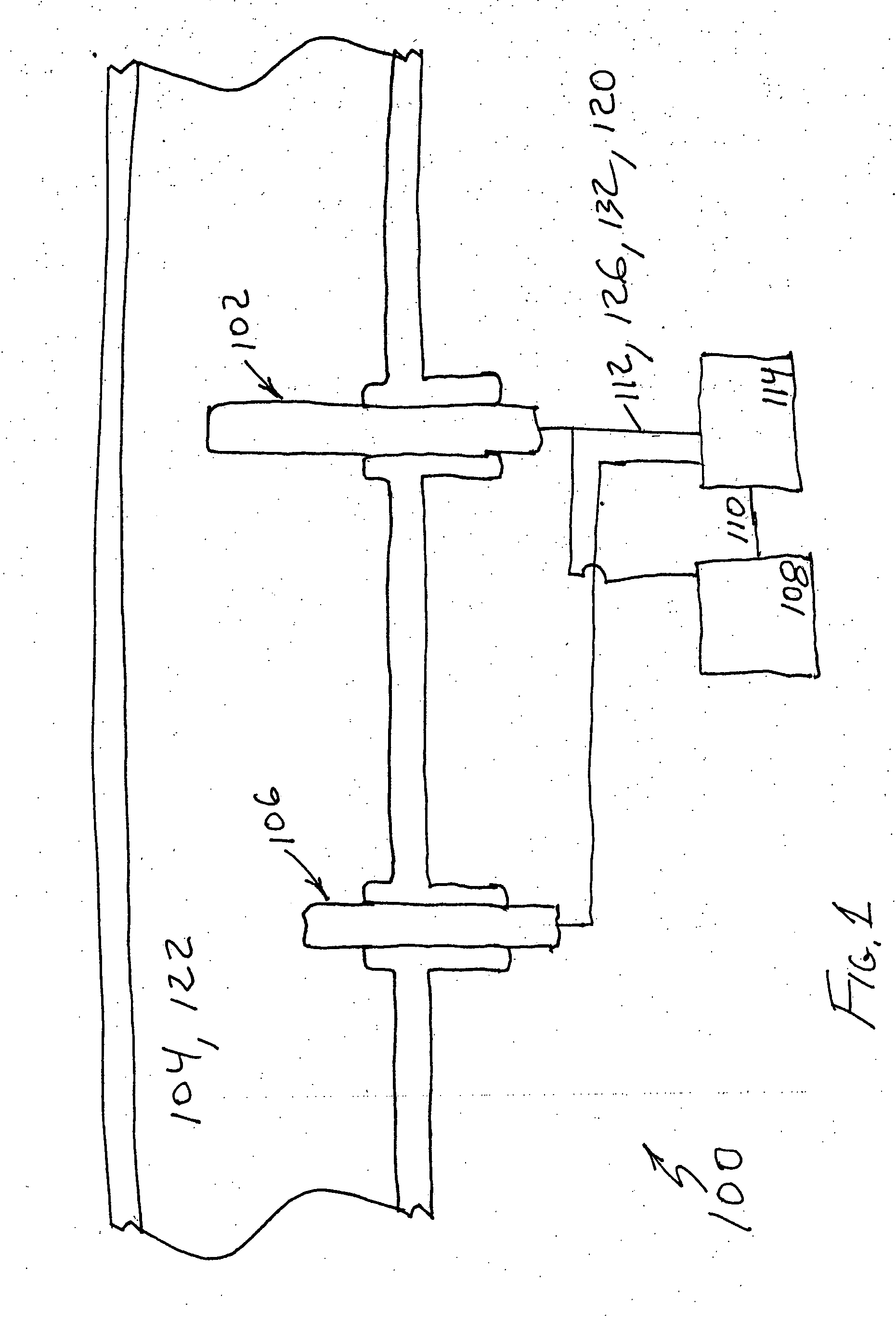
[0026] In FIG. 1 is shown a heating element protection apparatus for a mass-flow sensor 100 according to the invention. Mass-flow sensor 100 may include a heating element 102 disposed in a gas 104. A heating element controller 114 may supply power 112 to heating element 102 to replace heat dissipated by convection, conduction, or radiation to gas 104.

[0027] Since a rate of mass flow of gas 104 is proportional primarily to heat dissipated by convection, heating element controller 114 may assess the difference between a temperature 120 of heating element 102 and the gas temperature to compensate for the heat dissipated by conduction and radiation. In one embodiment, a gas temperature sensor 106 may be disposed in gas 104 to sense temperature 122 of gas 104. In this embodiment heating element controller 114 may detect temperature 120 of heating element 102 and may supply power 112 to heating element 102 based on heating element temperature 120 and gas temperature 122. In another embodi...

second embodiment

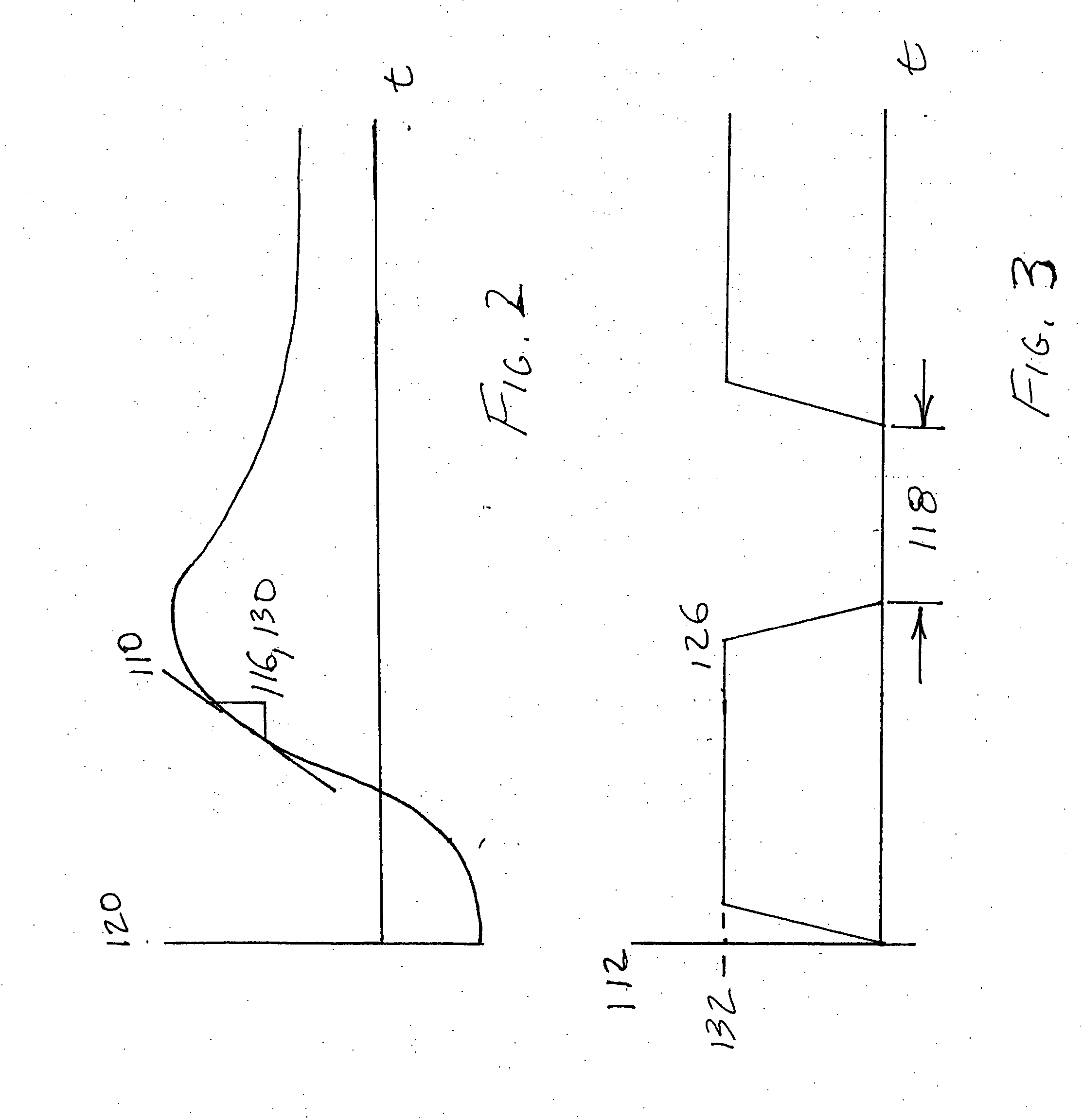
[0033] In the invention a method of protecting a heating element 100 for a mass-flow sensor 100 may include the steps of disposing a heating element 102 in a gas 104, detecting a temperature 120 of heating element 102, disposing a gas temperature sensor 106 in gas 104, sensing a temperature 122 of gas 104, supplying power 112 to heating element 102 to replace heat dissipated by gas 104 based on heating element temperature 120 and gas temperature 122, measuring a slope 110 of power 112 with a slope detector 108 as it is supplied to heating element 102, and switching off power 112 for a predetermined period of time 118 if a magnitude of slope 110 may be greater than a reference magnitude 124. In one embodiment, the method of protecting a heating element 100 for a mass-flow sensor 100 may further include the step of restarting an open loop ramp up.


PUM


Abstract

A heating element protection apparatus for a mass-flow sensor may include a heating element disposed in a gas, a gas temperature sensor disposed in the gas to sense a temperature of the gas, a slope detector to measure a slope of the temperature as power is supplied to the heating element, and a heating element controller to supply power to the heating element to replace heat dissipated by the gas. The heating element controller may detect a temperature of the heating element and may supply power to the heating element based on the heating element temperature and the gas temperature, and the power may be switched off for a predetermined period of time if a magnitude of the slope is greater than a reference magnitude.

Description

BACKGROUND OF THE INVENTION [0001] 1. Field of the Invention [0002] The invention relates to mass-flow sensor heating elements in general, and to protecting heating elements in mass flow sensors from thermal shock. [0003] 2. Description of the Related Art [0004] Emission control standards for internal combustion engines have tended to become more stringent over time. One type of emissions is known as oxides of nitrogen (NOx). Oxides of nitrogen tend to be produced by efficient, complete combustion. Efficient, complete combustion tends to be characterized by high combustion chamber temperatures. The heat associated with high combustion chamber temperatures acts as a catalyst, promoting the binding of oxygen in the air charge to the otherwise inert nitrogen and producing oxides of nitrogen. An engine that is running efficiently, therefore, may produce oxides of nitrogen. Controlling the amounts of emissions produced by an internal combustion engine, then, becomes an issue of balancing...

Claims


Application Information

Patent Timeline
IPC IPC(8): F02D41/18G01F1/698H05B1/02
CPCF02D41/187G01F1/6986G01F1/698
Inventor GRIFFIN, JOSEPH R.GANSEMAN, CHRISVOORDE, PATRICK VAN DEBURKHOLDER, NELSON R.GEYER, STEPHEN M.
Owner VOLVO LASTVAGNAR AB
Why Eureka
Try Eureka