Stage devices and exposure systems comprising same

a technology of exposure system and stage device, which is applied in the field of stage device and exposure system comprising, can solve the problems of low positioning stability, large magnetic field disturbance on the stage, and high cost of linear motor, and achieve the effect of enhancing stage positioning precision and improving stage controllability

Inactive Publication Date: 2005-09-01
NIKON CORP
View PDF2 Cites 15 Cited by
  • Summary
  • Abstract
  • Description
  • Claims
  • Application Information

AI Technical Summary

Benefits of technology

[0011] Because linear motors exhibit excellent linearity, they allow high-precision positioning control and speed-following control. However, linear motors are expensive, produce leaky magnetic fields, and have low positioning stability. In particular, if the drive mechanism for an X-slider is configured as an ordinary linear motor, the permanent magnets of the linear motor will move together with the Y-sliders or with the movement guides, which produces a large magnetic-field disturbance on the stage. Such a magnetic-field disturbance is intolerable whenever the stage device is used in a charged-particle-beam exposure system. By configuring the actuator for the drive mechanism for the X-slider as one that does not produce an electromagnetic force, such as an air cylinder, magnetic-field disturbances produced on the stage whenever the Y-sliders are being driven are insignificant, which allows high-precision exposures to be performed. Also, because the stators (permanent magnets) of the drive actuator of the Y-sliders are fixed on a stationary plate along the fixed guides, and because they are comparatively distant from the stage unit, adverse magnetic effects can be minimized even if the Y-sliders are driven using a linear motor.
[0034] The stage device can further include secondary fixed guides for guiding the auxiliary sliders. The secondary fixed guides are deployed in parallel with the fixed guides. An active countermass can be driven by a drive mechanism in a direction opposite to that of the auxiliary sliders. The drive mechanism is deployed inside the secondary fixed guides. The active countermass deployed inside the secondary guides cancels recoil and suppresses vibrations associated with the secondary slider drive, which enhance stage-positioning precision.

Problems solved by technology

However, linear motors are expensive, produce leaky magnetic fields, and have low positioning stability.
In particular, if the drive mechanism for an X-slider is configured as an ordinary linear motor, the permanent magnets of the linear motor will move together with the Y-sliders or with the movement guides, which produces a large magnetic-field disturbance on the stage.
Such a magnetic-field disturbance is intolerable whenever the stage device is used in a charged-particle-beam exposure system.

Method used


Image

  • Stage devices and exposure systems comprising same
  • Stage devices and exposure systems comprising same
  • Stage devices and exposure systems comprising same

Examples


first embodiment

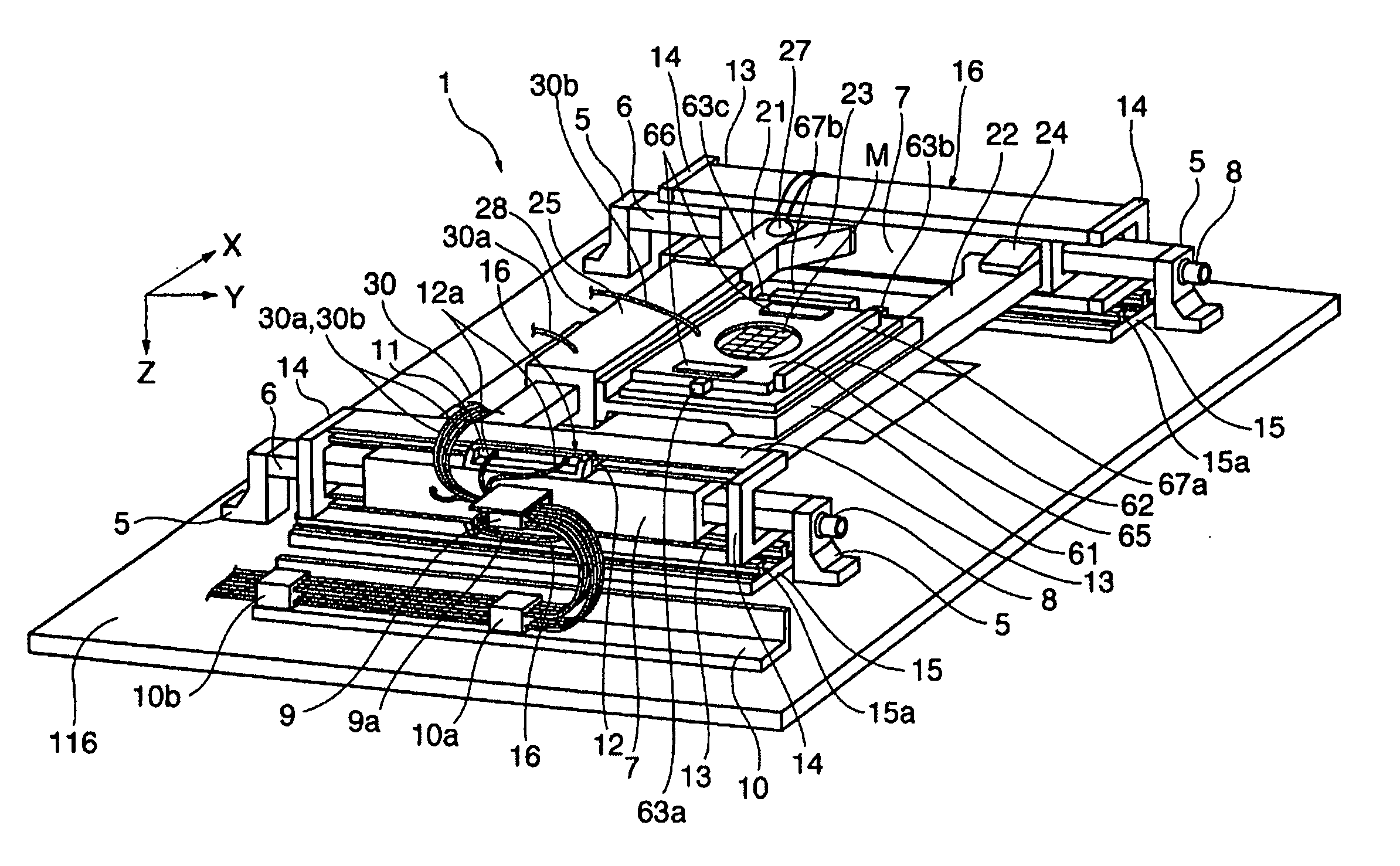
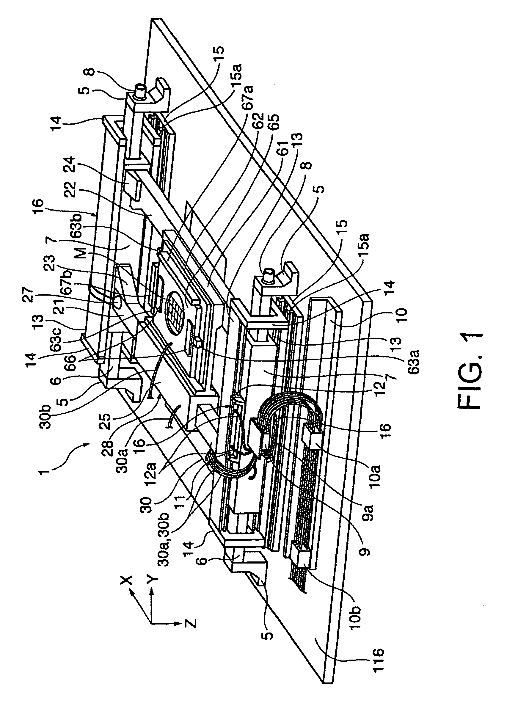
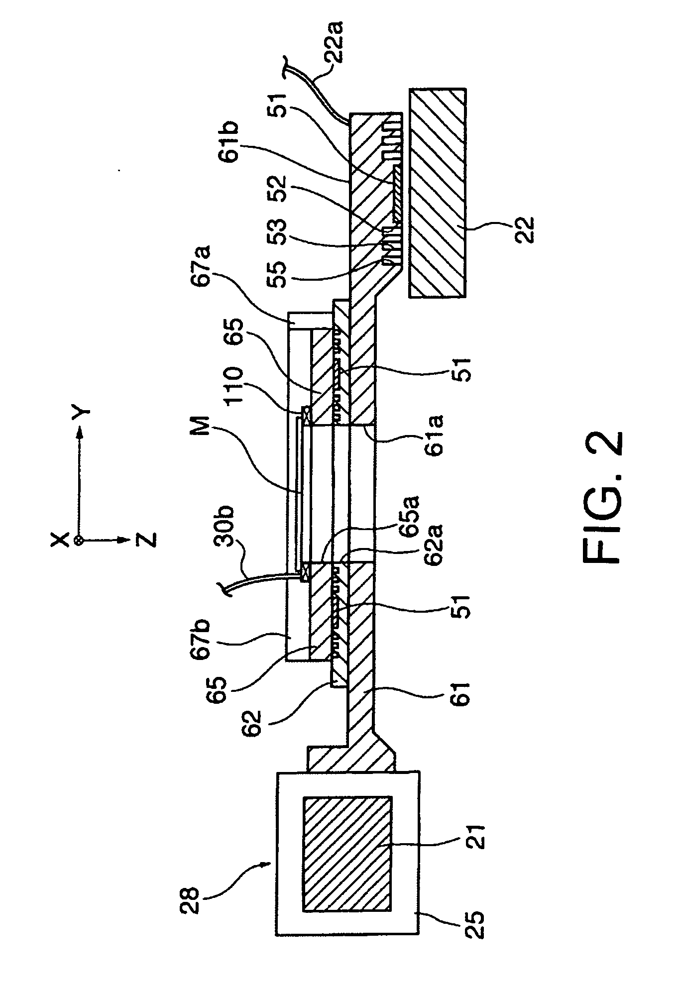
[0078] A stage device is described with reference to FIGS. 1, 2, and 3. FIG. 1 is a perspective view of the overall configuration of the stage device, FIG. 2 is a side elevational section of an X-slider and stage unit of the stage device, and FIG. 3 is a side elevational section of a Y-slider of the stage device.

[0079] In FIG. 1 the stage device 1 is mounted on a stationary plate 116 (see FIG. 6) that extends in the XY plane. The stage device 1 corresponds to the mask stage 111 in the exposure system of FIG. 6. At two places on the upper surface of the stationary plate 116, two fixed guides 6 are secured that extend parallel to each other in the Y-direction. The fixed guides 6 are respectively secured by two guide-securing brackets 5 so as to be in opposition to each other. The two fixed guides 6 and their peripheral members are configured in basically the same way. Onto the fixed guides 6, Y-sliders 7 of a hollow-box shape are fitted so that they can slide in the Y-direction while...

second embodiment

[0100] Next, a stage device is described with reference to FIG. 7. This is an example in which the top and bottom of the stage 61 of the stage device 1, on the side opposite the movement guide, are configured as constraining guides with gas bearings. FIG. 7 is a side-elevational section of the X-slider and stage unit of the stage device of this embodiment. The configuration of most of the stage device of FIG. 7 is the same as of the stage device 1 shown in FIG. 1. Hence, components that are the same in both embodiments have the same reference numerals and are not described further.

[0101]FIG. 7 shows the X-slider 25 fitted onto the movement guide 21. A stage 61′ is attached to a side surface on the inner side of the X-slider 25. On the side (leading-edge part) of the X-slider 25, opposite the stage 61′, is a movement guide 22′ extending in the X-direction. The cross-section of the movement guide 22′ is shaped as a flat sideways “U”.

[0102] The stage 61′ defines a through-hole 61 a′ ...

third embodiment

[0104] Next, a stage device is described with reference to FIG. 8. FIG. 8 is a perspective view of the overall configuration of a stage device according to this embodiment. This stage device is an example in which a 4-degree-of-freedom (4-DOF) micro-movement stage is mounted on an XY stage. The configuration of most of this stage device is the same as of the stage device 1 shown in FIG. 1. Hence, components that are the same in both embodiments have the same reference numerals and are not described further. In the depicted stage device, hydraulic lines and connecting wires are omitted from the drawing.

[0105]FIG. 8 shows two fixed guides 6 that are mounted on the stationary plate 116 (see FIG. 6) and Y-sliders 7 that are fitted onto the fixed guides 6. The Y-sliders 7 are driven in the Y-direction on the fixed guides 6 by linear motors 16. In this example, moreover, the two coil joints 12 and movable coils 12b (see FIG. 3) of the linear motors 16 are secured to coil-securing plates ...


PUM

PropertyMeasurementUnit
mass ratioaaaaaaaaaa
pressureaaaaaaaaaa
propulsionaaaaaaaaaa

Abstract

Stage devices are disclosed that can be made small and lightweight and that produce little magnetic-field disturbance. As a result, high-precision scan positioning can be performed using them. In an exemplary configuration, a Y-slider driven by a linear motor is deployed on each of two fixed guides that extend in the Y-direction. Between the two Y-sliders are suspended two movement guides that extend in the X-direction. On the movement guide is an X-slider driven by an air cylinder. A stage projects from the X-slider. On the stage is a table driven in the O,-direction (about the Z-axis). The stage device is configured so that a continuous movement (scan) requiring precise positioning is achieved in the Y-direction by linear motors, and intermittent movement and stopping in the X-direction is achieved using an air cylinder.

Description

CROSS-REFERENCE TO RELATED APPLICATIONS [0001] This is a continuation of International Application No. PCT / JP2003 / 012136, filed Sep. 24, 2003, which is incorporated herein in its entirety.FIELD [0002] This disclosure relates to stage devices for moving and positioning a pattern-master plate (mask, reticle) or sensitive substrate (wafer) or the like, and to exposure systems equipped with such stage devices. More particularly, this disclosure relates to stage devices that produce low magnetic-field disturbance, that can be made small and lightweight, and that can perform high-precision positioning for scanning purposes. BACKGROUND [0003] Most of the stage devices for current exposure systems employing light are either so-called “H-type” or “I-type” X-Y stage devices. In these stage devices, a movement guide is suspended between two fixed guides that extend in parallel in a given direction, and a self-propelled stage is configured to travel on the movement guide. The “H” and “I” design...

Claims


Application Information

Patent Timeline
Patent Type & Authority Applications(United States)
IPC IPC(8): G03F7/20
CPCB82Y10/00B82Y40/00G03F7/70716G03F7/70758H01J2237/20221H01J37/20H01J37/3174H01J2237/2005H01J2237/202G03F7/70858
Inventor TANAKA, KEIICHI
Owner NIKON CORP
Why Eureka
Try Eureka