Optical remote sensor with differential Doppler motion compensation

a technology of optical remote sensor and doppler, applied in the direction of fluid speed measurement, instruments, measurement devices, etc., can solve the problems of complex attempt to determine the net global motion of components in an ensemble of dynamically moving scattering sites, inhibit the optimum performance of the sensor, and unattractive in many applications, so as to achieve the effect of suppressing noise components

Inactive Publication Date: 2005-09-01
HRL LAB
View PDF5 Cites 9 Cited by
  • Summary
  • Abstract
  • Description
  • Claims
  • Application Information

AI Technical Summary

Benefits of technology

[0009] In another aspect, the presently disclosed technology relates to an optical system for suppressing noise components produced by an ensemble of dynamically moving scattering sites which has a laser probe source; a scattering medium under inspection, which is illuminated by the laser probe source; a wavefront-reversal device for collecting light reflected from the scattering medium and returning a conjugated beam; and an optical detector for detecting and processing the conjugated beam reflected from the scattering medium.

Problems solved by technology

The attempt to determine the net global motion of components in an ensemble of dynamically moving scattering sites has proved to be complex, given that many ensembles of scattering sites possess two modes of motion: a global velocity component and a differential velocity component.
It is the presence of the random motion that adds noise to the system and inhibits the optimum performance of the sensor.
Currently, the prior art that exists in remote sensors involves complex adaptive optical compensation systems and light detection and ranging (lidar) approaches.
These approaches require intensive post processing which makes them unattractive in many applications.

Method used


Image

  • Optical remote sensor with differential Doppler motion compensation
  • Optical remote sensor with differential Doppler motion compensation
  • Optical remote sensor with differential Doppler motion compensation

Examples


Embodiment Construction

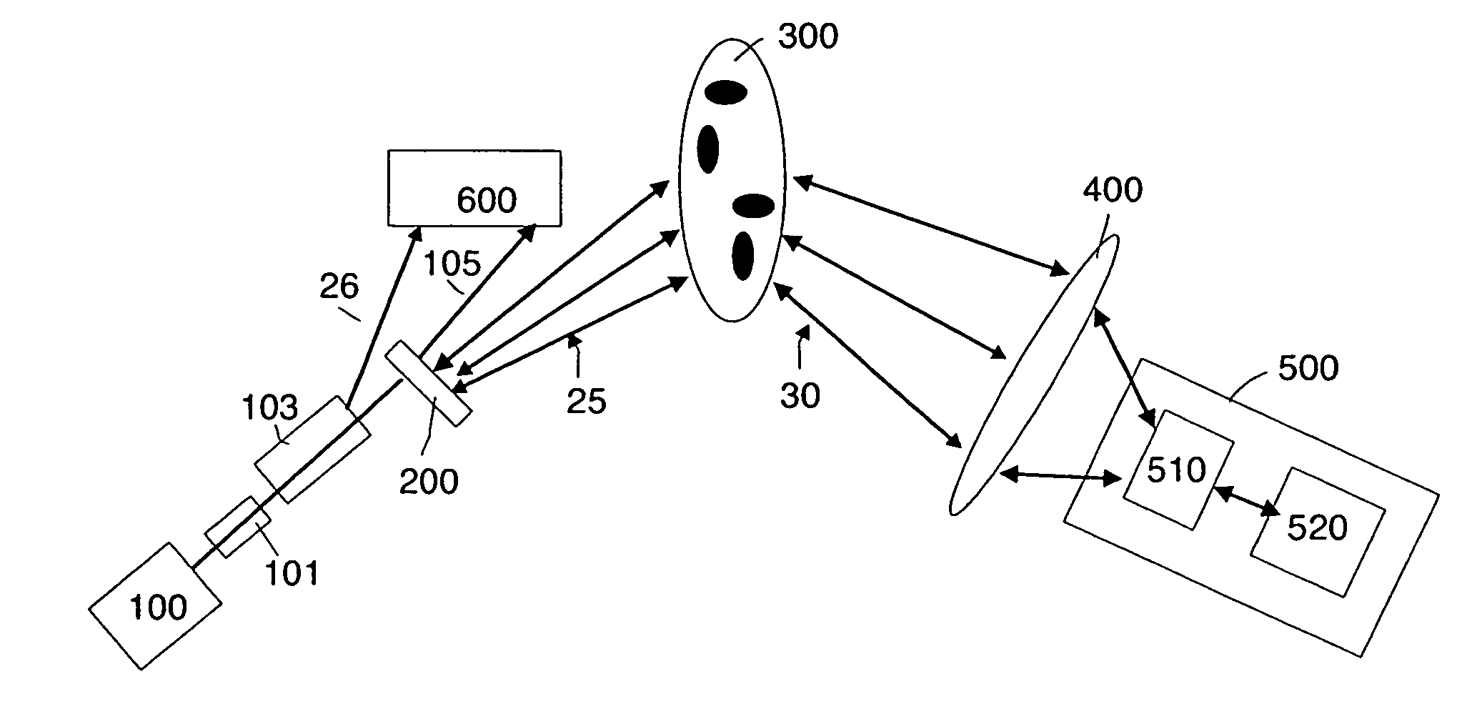
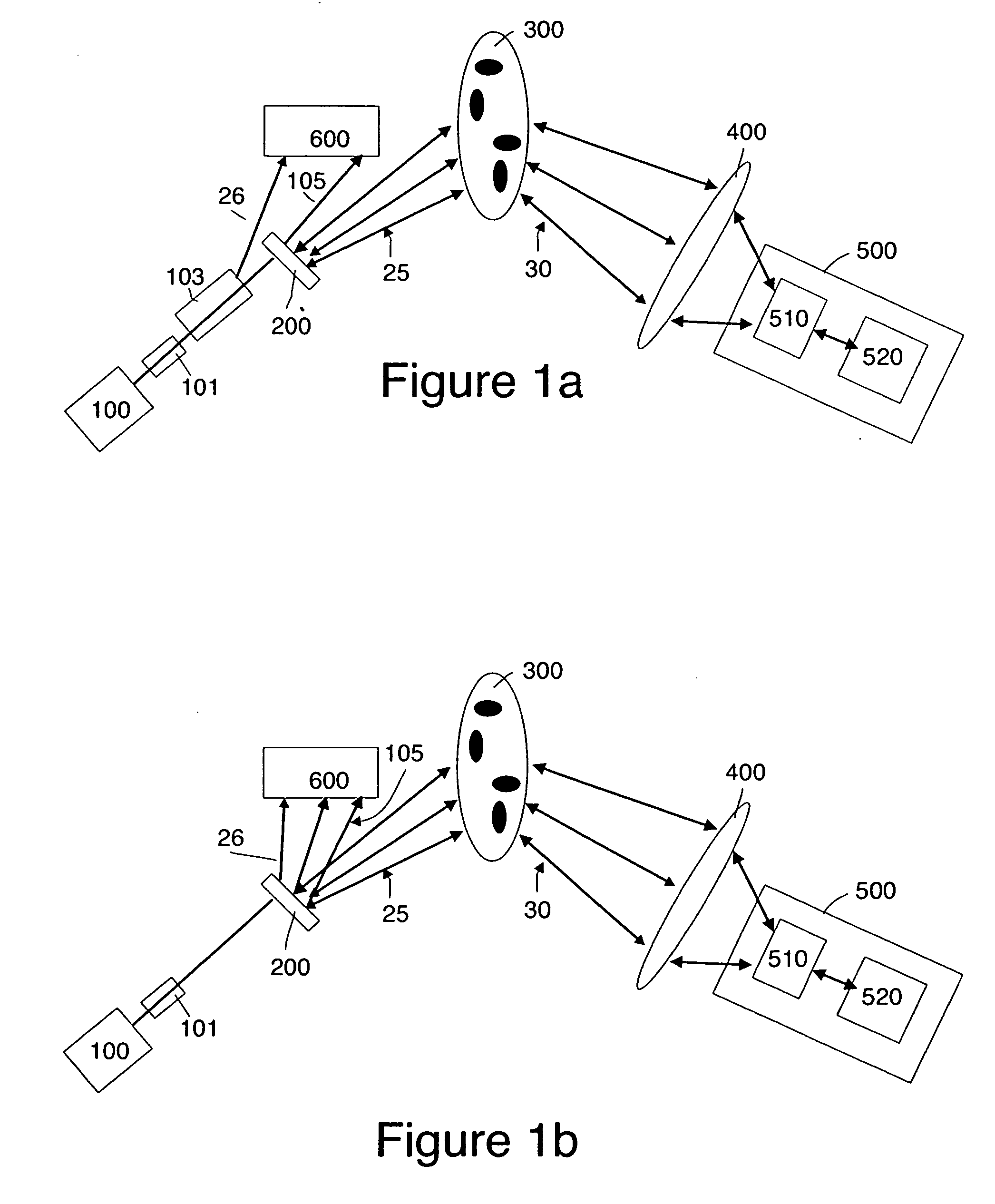
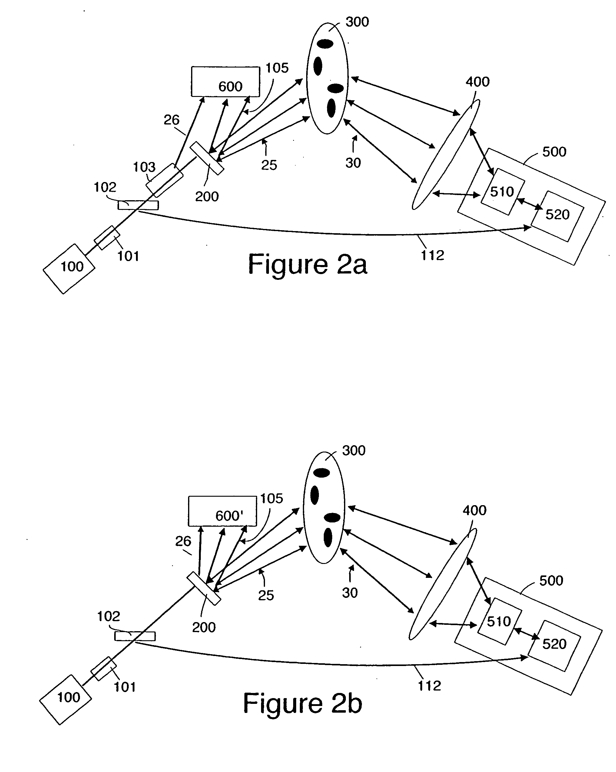
[0020]FIG. 1a is a schematic diagram of the basic system architecture of one embodiment of the presently disclosed technology, utilizing a self-pumped Phase Conjugate Mirror (PCM) in a wavefront-reversal module 500 and a heterodyne detector 600. A laser beam from a probe laser 100, which laser may be implemented by a diode-pumped solid state laser, an argon ion laser, a laser diode or other lasing device, is preferably passed via an optical isolater 101 to an Acousto-Optic (AO) modulator 103. The optical isolater 101 is preferably utilized to prevent reflected beams from re-entering the probe laser 100 which could otherwise cause instability in the probe laser 100. The AO modulator 103 generates a local oscillator (LO) reference signal 26 that is offset in frequency from the signal beam for heterodyne detection of a received signal 105 by a heterodyne detector 600. As will be seen, the received signal 105 reflects off the surface of beam splitter 200 in this embodiment. Those skille...


PUM


Abstract

A system and a method for remotely sensing global motion of an ensemble of dynamically moving scattering sites. The system comprising a scattering medium under inspection, an optical transceiver and a detector in a double-pass geometry.

Description

CROSS REFERENCE TO RELATED APPLICATION [0001] This application is relates to U.S. patent application Ser. No. 09 / 849,641 filed May 4, 2001, entitled “Vibrometer System Using a Phase Conjugate Mirror” this disclosure of which is hereby incorporated herein by reference. TECHNOLOGICAL FIELD [0002] The technology disclosed herein relates to a system for and method of sensing net global motion of components in an ensemble of dynamically moving scattering sites. This technology is useful for remote sensing and reconnaissance data acquisition applications in various scattering systems, including ocean water, fog, clouds, suspensions, biological samples, as well as liquid and gaseous flow monitoring systems. BACKGROUND INFORMATION [0003] The attempt to determine the net global motion of components in an ensemble of dynamically moving scattering sites has proved to be complex, given that many ensembles of scattering sites possess two modes of motion: a global velocity component and a differe...

Claims


Application Information

Patent Timeline
Patent Type & Authority Applications(United States)
IPC IPC(8): G01B9/02G01P5/26G01S17/50
CPCG01S17/50G01P5/26
Inventor PEPPER, DAVID M.MINDEN, MONICADUNNING, GILMORE J.
Owner HRL LAB
Why Eureka
Try Eureka