Catadioptric projection objective

a catadioptric and objective technology, applied in the field of catadioptric projection objectives, can solve the problems of insufficient color correction, insufficient transparency of purely refractive systems, and difficulty in providing sufficiently well color correction systems, and achieve the effect of small amount of optical materials and high image side numerical apertures

Active Publication Date: 2005-09-01
CARL ZEISS SMT GMBH
View PDF37 Cites 685 Cited by
  • Summary
  • Abstract
  • Description
  • Claims
  • Application Information

AI Technical Summary

Benefits of technology

[0020] It is one object of the invention to provide a catadioptric projection objective suitable for use in the vacuum ultraviolet (VUV) range having potential for very high image side numerical aperture which may be extended to values allowing immersion lithography at numerical apertures NA>1. It is another object of the invention to provide catadioptric projection objectives that can be build with relatively small amounts of optical material.

Problems solved by technology

However, there are very few materials, in particular, synthetic quartz glass and crystalline fluorides, that are sufficiently transparent in that wavelength region available for fabricating the optical elements required.
Since the Abbe numbers of those materials that are available lie rather close to one another, it is difficult to provide purely refractive systems that are sufficiently well color-corrected (corrected for chromatic aberrations).
The high prices of the materials involved and limited availability of crystalline calcium fluoride in sizes large enough for fabricating large lenses represent problems, particularly in the field of microlithography at 157 nm for very large numerical apertures, NA, of, for example, NA=0.80 and larger.
However, since the reflecting surfaces of the concave mirrors are interrupted at the bores, the pupil of the system is obscured.
The authors conclude that physically realizable systems of this type have poor image quality.

Method used


Image

  • Catadioptric projection objective
  • Catadioptric projection objective
  • Catadioptric projection objective

Examples


first embodiment

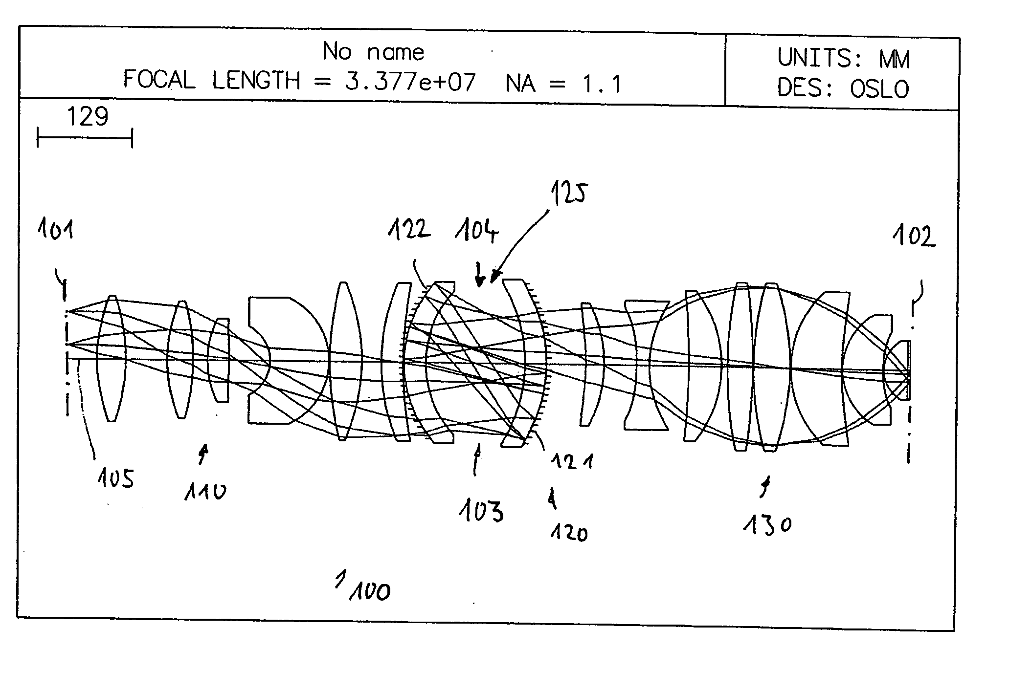
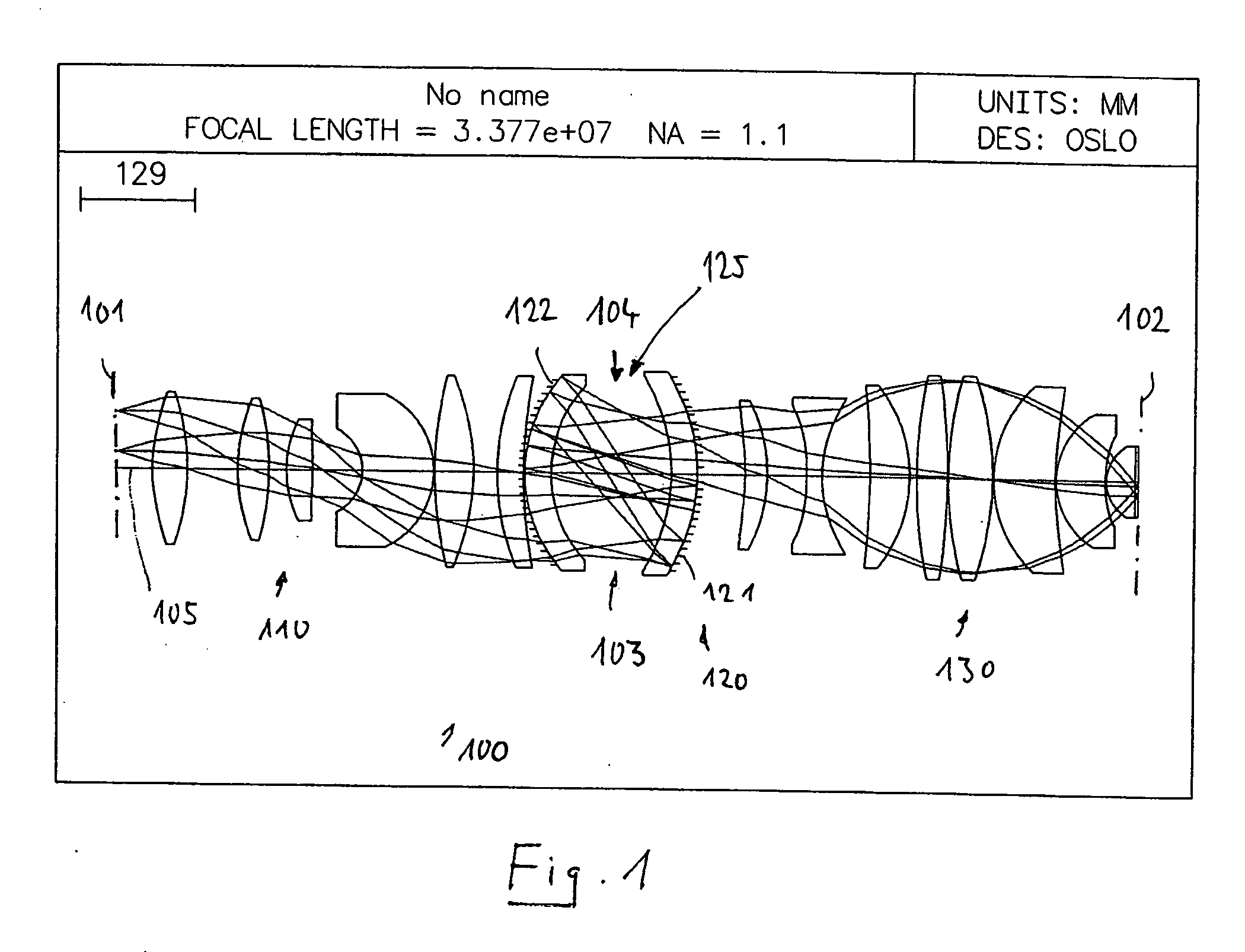
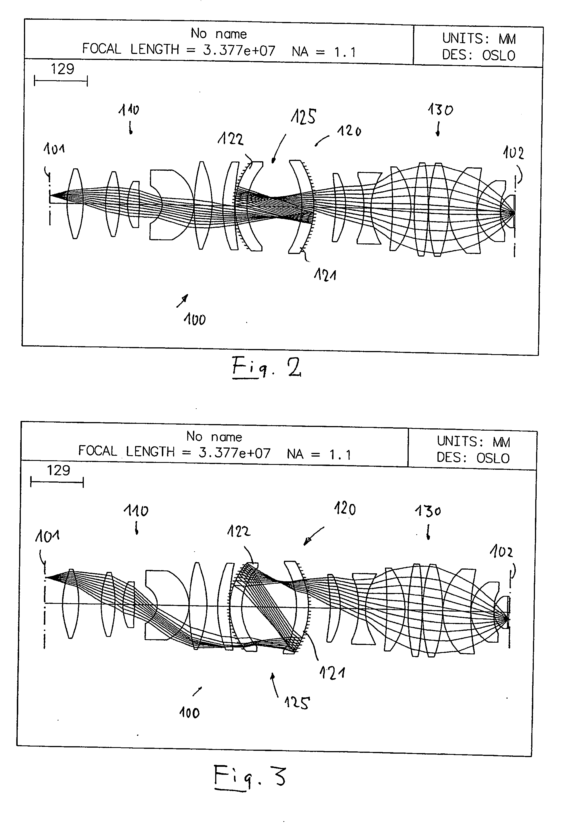
[0129]FIG. 1 shows a catadioptric projection lens 100 according to the invention designed for ca. 193 nm UV working wavelength. It is designed to project an image of a pattern on a reticle arranged in the object plane 101 into the image plane 102 on a reduced scale, for example, 4:1, while creating exactly two real intermediate images 103, 104. A first refractive objective part 110 is designed for imaging the pattern in the object plane into the first intermediate image 103 at an enlarged scale, a second, catadioptric objective part 120 images the first intermediate image 103 into the second intermediate image 104 at a magnification close to 1:1, and a third, refractive objective part 130 images the second intermediate image 104 onto the image plane 102 with a strong reduction ratio. The second objective part 120 comprises a first concave mirror 121 having the concave mirror surface facing the object side, and a second concave mirror 122 having the concave mirror surface facing the ...

second embodiment

[0140] In FIG. 4 a second embodiment is shown. Features or feature groups identical or similar in structure and / or function to those in FIG. 1 are denoted by similar numerals increased by 100.

[0141] The projection objective 200 is designed as an immersion lens for λ=193 nm having an image side numerical aperture NA=1.20 when used in conjunction with a high index immersion fluid, e.g. pure water, between the exit face of the objective and the image plane. The field size is 26·5.0 mm2. The specifications for this design are summarized in Table 4. The leftmost column lists the number of the refractive, reflective, or otherwise designated surface, the second column lists the radius, r, of that surface [mm], the third column lists the distance, d [mm], between that surface and the next surface, a parameter that is referred to as the “thickness” of the optical element, the fourth column lists the material employed for fabricating that optical element, and the fifth column lists the refrac...

third embodiment

[0151] In FIG. 10 a third embodiment is shown. Features or feature groups identical or similar in structure and / or function to those in FIG. 1 are denoted by similar numerals increased by 200. FIG. 11 represents a longitudinal sectional view of an embodiment designed on the basis depicted in FIG. 10.

[0152] The embodiment of a catadioptric projection objective 300 in FIG. 10 is similar to some of the above mentioned embodiments in that it comprises a first, refractive objective part 310 for creating a first intermediate image 303, a second, catoptric objective part 320 for creating a second intermediate image 304 from the first intermediate image, and a third, refractive objective part 330 for re-imaging the second intermediate image onto the image plane 302. The second objective part may include at least one lens such that it becomes a catadioptric objective part.

[0153] In contrast to the embodiments shown above, the second objective part 320 includes four reflective surfaces, name...


PUM

PropertyMeasurementUnit
refractive indexaaaaaaaaaa
wavelength rangeaaaaaaaaaa
wavelengthsaaaaaaaaaa

Abstract

A catadioptric projection objective for imaging a pattern provided in an object plane of the projection objective onto an image plane of the projection objective comprises: a first objective part for imaging the pattern provided in the object plane into a first intermediate image; a second objective part for imaging the first intermediate imaging into a second intermediate image; a third objective part for imaging the second intermediate imaging directly onto the image plane; wherein a first concave mirror having a first continuous mirror surface and at least one second concave mirror having a second continuous mirror surface are arranged upstream of the second intermediate image; pupil surfaces are formed between the object plane and the first intermediate image, between the first and the second intermediate image and between the second intermediate image and the image plane; and all concave mirrors are arranged optically remote from a pupil surface. The system has potential for very high numerical apertures at moderate lens material mass consumption.

Description

[0001] The present application claims priority benefit to U.S. Provisional 60 / 536,248 filed Jan. 14, 2004; U.S. Provisional 60 / 587,504 filed Jul. 14, 2004; U.S. Provisional 60 / 617,674 filed Oct. 13, 2004; U.S. Provisional 60 / 591,775 filed Jul. 27, 2004; and U.S. Provisional 60 / 612,823 filed Sep. 24, 2004. The disclosures of all of these Provisional applications are incorporated into this application by reference.BACKGROUND OF THE INVENTION [0002] 1. Field of the Invention [0003] The invention relates to a catadioptric projection objective for imaging a pattern arranged in an object plane onto an image plane. [0004] 2. Description of the Related Art [0005] Projection objectives of that type are employed on projection exposure systems, in particular wafer scanners or wafer steppers, used for fabricating semiconductor devices and other types of microdevices and serve to project patterns on photomasks or reticles, hereinafter referred to generically as “masks” or “reticles,” onto an obj...

Claims


Application Information

Patent Timeline
Patent Type & Authority Applications(United States)
IPC IPC(8): G02B17/08G03F7/20
CPCG02B13/22G02B17/0812G02B17/0892G03F7/70966G03F7/70275G03F7/70341G03F7/70958G03F7/70225G02B13/18G02B17/004H01L21/0273H01L21/0274
Inventor SHAFER, DAVIDULRICH, WILHELMDODOC, AURELIANVON BUENAU, RUDOLFMANN, HANS-JUERGENEPPLE, ALEXANDER
Owner CARL ZEISS SMT GMBH
Why Eureka
Try Eureka