Video multiplexer system providing low-latency VCR-like effects and program changes

a video multiplexer and low-latency technology, applied in frequency-division multiplexing, data switching networks, instruments, etc., can solve problems such as difficult introduction of technological innovations, high-speed, high-performance processing, data routing, etc., and achieve the effect of minimizing visual disruption of the displayed video imag

Active Publication Date: 2005-09-01
IMAGINE COMM
View PDF57 Cites 128 Cited by
  • Summary
  • Abstract
  • Description
  • Claims
  • Application Information

AI Technical Summary

Benefits of technology

[0014] The present inventive technique accommodates this with minimal modification to existing digital cable infrastructure by inserting “start-of-segment” identifiers at the beginning of new video segments. These identifiers serve to mark transition points where multiplexing hardware can rapidly switch over to the new video stream. These identifiers can be made compatible with existing cueing message protocols, but differ from “conventional” cueing in that there is no need to mark “exit” points in the video stream being abandoned. The multiplexer is notified in advance of the transition and need only monitor the new video segment for an indication of when to make the switch.
[0015] When the multiplexer makes the switch, buffers associated with the “old” video stream are flushed, and restoration of buffer levels with video data from the new stream begins. This is accomplished by transmitting video associated with the new stream at a rate faster than real-time (i.e., faster than is needed to display the video data) until buffer levels have once again built up to desired levels. This can be controlled in several ways. One option is to simply cause the video server providing the new stream data to transmit the new stream at an elevated data rate for a fixed period of time after effecting a video transition, thereby causing accumulation (buffering) of “excess” (beyond immediate requirements) video data to occur. After a period of time chosen to cause accumulation of an appropriate amount of video data, transmission rates can be reduced to be consistent with “real-time” video requirements.
[0019] According to an aspect of the invention, the identifier can be cueing message packet. In order to minimize communications and video processing overhead, identification packets can be indicated with a fixed packet ID (PID). To maximize compatibility with existing protocols and mechanisms, cueing message packet can be made compliant with ANSI / SCTE 35. For example, a splice_insert message with a splice_immediate indication set to 1 can be used to indicate a start-of-segment for a transition.
[0020] Although it is preferred that start-of-segment identifier occur synchronously with reference frames, if such a condition does not occur, the multiplexer can delay transitioning until the first reference frame following an identifier. This minimizes visual disruption to the displayed video image, creating a more seamless appearance to the transition. Clients (i.e., set-top boxes) connect to the distribution network for the purpose of receiving and displaying video content on a user's television screen or monitor.

Problems solved by technology

Clearly, this requires a great deal of high-speed, high-performance processing, data routing, encoding and multiplexing hardware that would not otherwise be required.
This can become problematic if relatively large numbers of viewers are equipped with on-demand capabilities and the content owners are deriving their compensation from revenues that originate from the advertisers.
Unfortunately, by limiting the number of vendors that have access to this market, it becomes more difficult to introduce technological innovations and a barrier is created for new entrants seeking to enter this market with more efficient products.
Unfortunately, this may not be possible if the cost of the encryption and decryption components remains high, or if these components continue to be manufactured in low density enclosures and are not integrated with other head-end equipment.

Method used


Image

  • Video multiplexer system providing low-latency VCR-like effects and program changes
  • Video multiplexer system providing low-latency VCR-like effects and program changes
  • Video multiplexer system providing low-latency VCR-like effects and program changes

Examples


Embodiment Construction

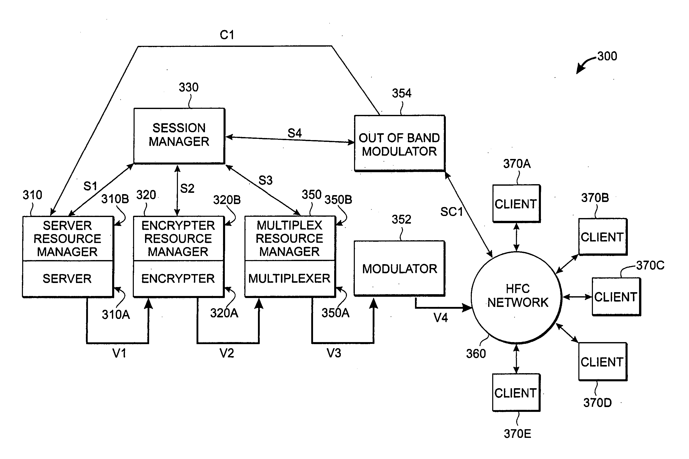
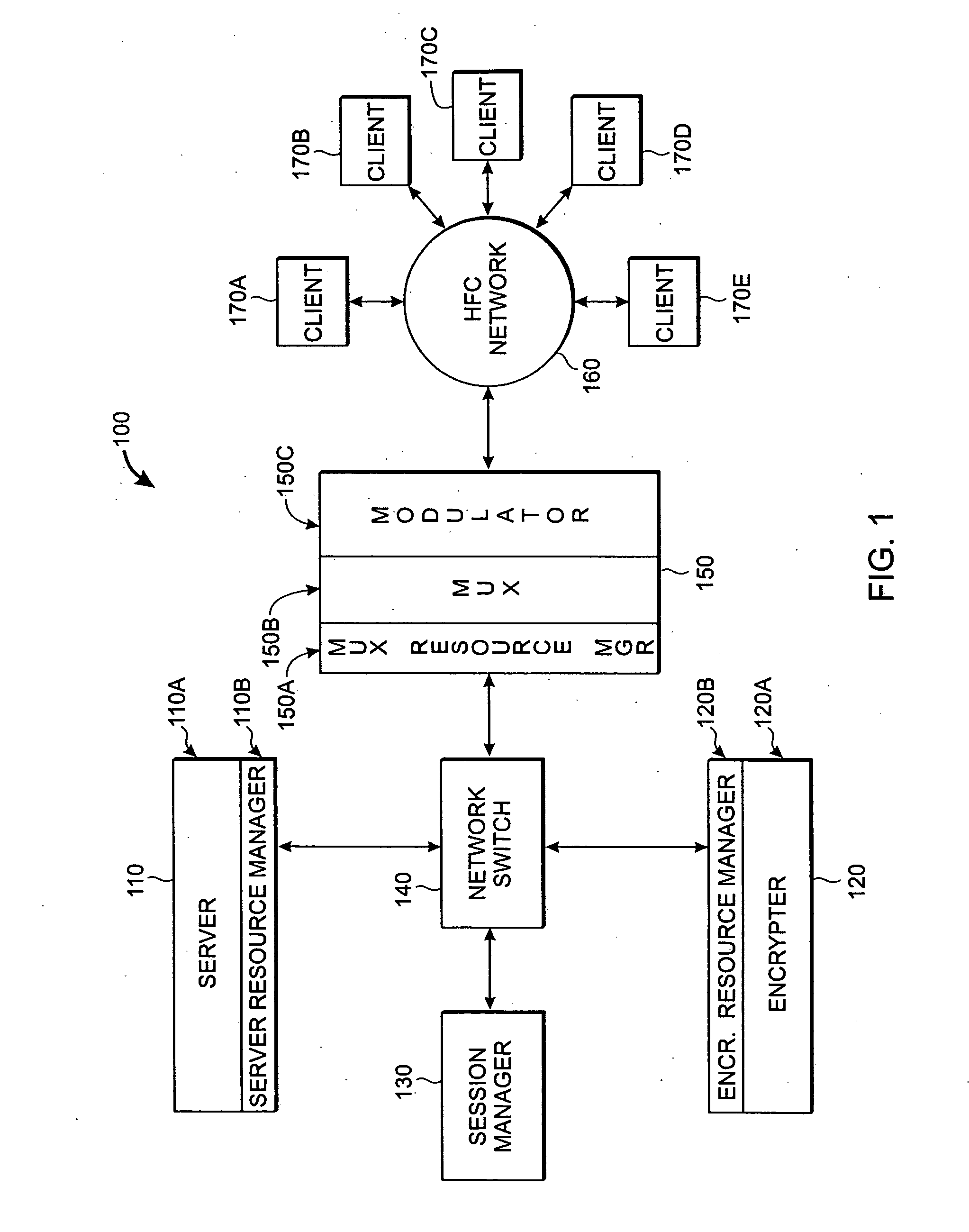
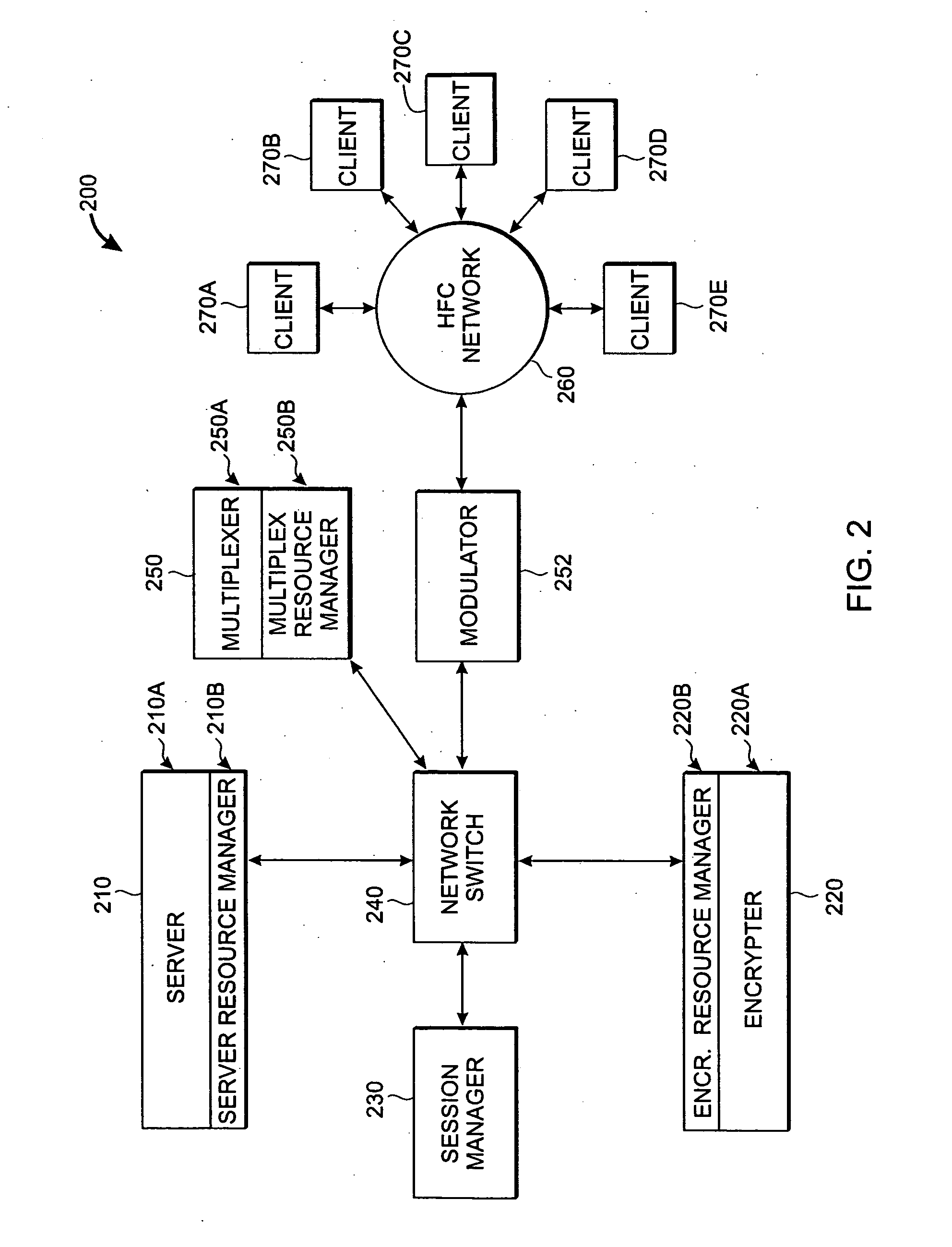
[0034] According to the present inventive technique, a video distribution system comprises one or more cable headends and small “edge” devices (i.e., all interconnected by a large metropolitan-area network. FIG. 1 is a block diagram of one embodiment of such a system 100. In FIG. 1, a “headend” network portion of the system 100 comprises server module 110, an “encrypter” module 120, a session manager 130, and a network switch 140. The network switch 140 provides connectivity between the various headend modules and any “edge” modules. In FIG. 1, a single representative edge module (150) is shown—an integrated multiplexer / modulator module 150 that acts as a network edge device to which a plurality of client devices 170A, 170B, 170C, 170D and 170E connect via a physical distribution system 160. The physical distribution system 160 provides “last mile” connectivity to the client devices located at end user locations, and is typically provided by a hybrid fiber / coax (HFC) or similar dist...


PUM


Abstract

An advanced multiplexer designed and optimized for next generation on-demand video distribution is described. Features and capabilities include low-latency client interactions, quality of service management, session based encryption management, support for multiple video formats, and support for multiple video decoding standards. Indicators are embedded in new video segments to identify start-of-segment transition points, enabling rapid transitions from one video segment to another. Low-latency operation is achieved by rapid switching, and by coordinating flushing of video buffers and buffer restoration.

Description

CROSS-REFERENCE TO RELATED APPLICATIONS [0001] This application claims the benefit of U.S. Provisional Patent Application No. 60 / 499,043 filed on Aug. 29, 2003, which is incorporated herein by reference. [0002] This application is a continuation of copending PCT Patent Application No. PCT / US 2004 / 028155 filed on Aug. 27, 2004, which is incorporated herein by reference. [0003] This application relates to copending PCT Patent Application No. PCT / US 2004 / 028031 filed on Aug. 27, 2004, which is incorporated herein by reference. [0004] This application relates to copending PCT Patent Application No. PCT / US 2004 / 028093 filed on Aug. 27, 2004, which is incorporated herein by reference.TECHNICAL FIELD OF THE INVENTION [0005] The present invention relates to video multiplexing systems, and more particularly to video multiplexing systems for digital cable television distribution. BACKGROUND [0006] Over the last several years, there has been considerable growth in the availability of digital c...

Claims


Application Information

Patent Timeline
Patent Type & Authority Applications(United States)
IPC IPC(8): G06F15/16G06F15/163H04B7/185H04H60/31H04JH04J1/00H04J3/26H04L12/16H04L12/26H04L12/28H04L12/66H04L29/06H04NH04N7/025H04N7/12H04N7/173H04N7/18H04N7/20H04N7/24H04N7/26H04N7/50H04N11/02H04N11/04
CPCH04L29/06027H04N19/40H04N7/1675H04N7/17318H04N7/17336H04N21/2225H04N21/23103H04N21/23424H04N21/2347H04N21/23608H04N21/2365H04N21/23655H04N21/2383H04N21/2385H04N21/2405H04N21/26216H04N21/26606H04N21/26613H04N21/4344H04N21/4347H04N21/44016H04N21/47202H04N21/6118H04N21/63345H04N21/812H04L65/605H04L65/4076H04L65/80H04N19/61H04N19/146H04N19/48H04L63/0428H04L65/611H04L65/765H04L65/1101
Inventor KRAUSE, EDWARD A.MONTA, PETERTOM, ADAM
Owner IMAGINE COMM
Why Eureka
Try Eureka