
Electrode assembly

a technology of electrolyte assembly and assembly plate, which is applied in the maintenance/servicing of primary cells, batteries, non-aqueous electrolyte cells, etc., can solve the problem that the conditions of pouch batteries are not optimal

Active Publication Date: 2005-09-01
QINETIQ LTD
View PDF8 Cites 75 Cited by
  • Summary
  • Abstract
  • Description
  • Claims
  • Application Information

AI Technical Summary

Benefits of technology

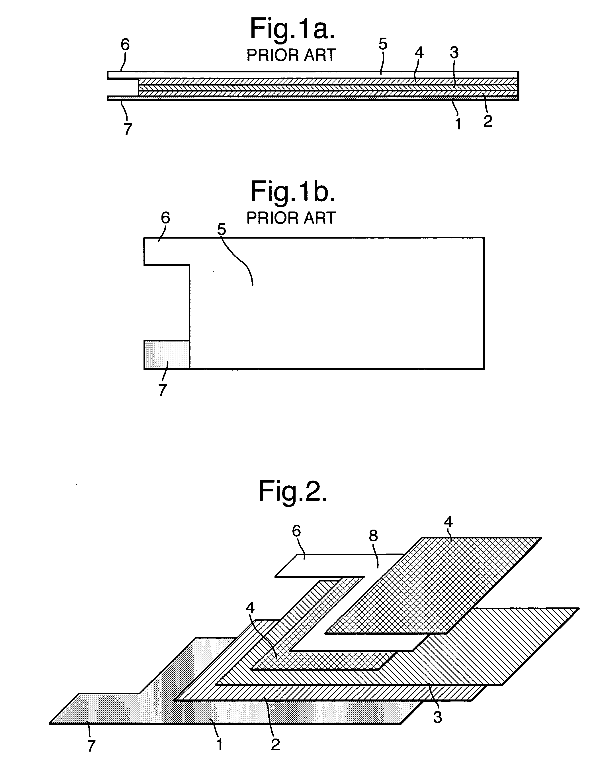
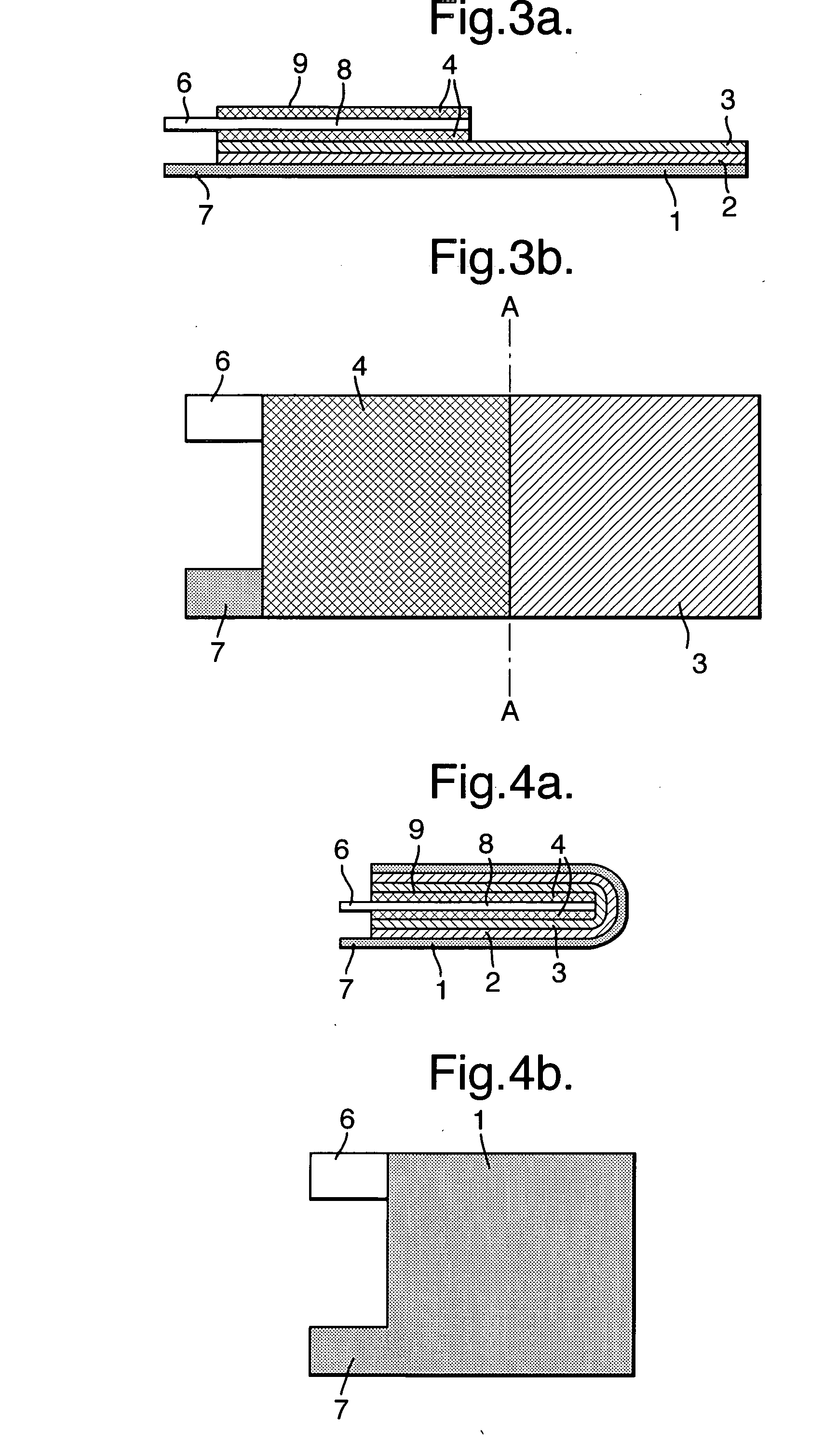
[0007] By employing a double-sided anode, significant improvements in energy density can be achieved, particularly where the anode comprises a single sheet current collector half the size of the cathode (as opposed to a current collector layer the same size as the other sheets, but folded in two); ideally the anode current collector's dimensions should correspond roughly to those of the cathode when folded in half perpendicular to its length. Moreover, by using a half sized anode that is active on both sides, the cathode capacity / cm2 can be reduced, leading to a number of other advantages.
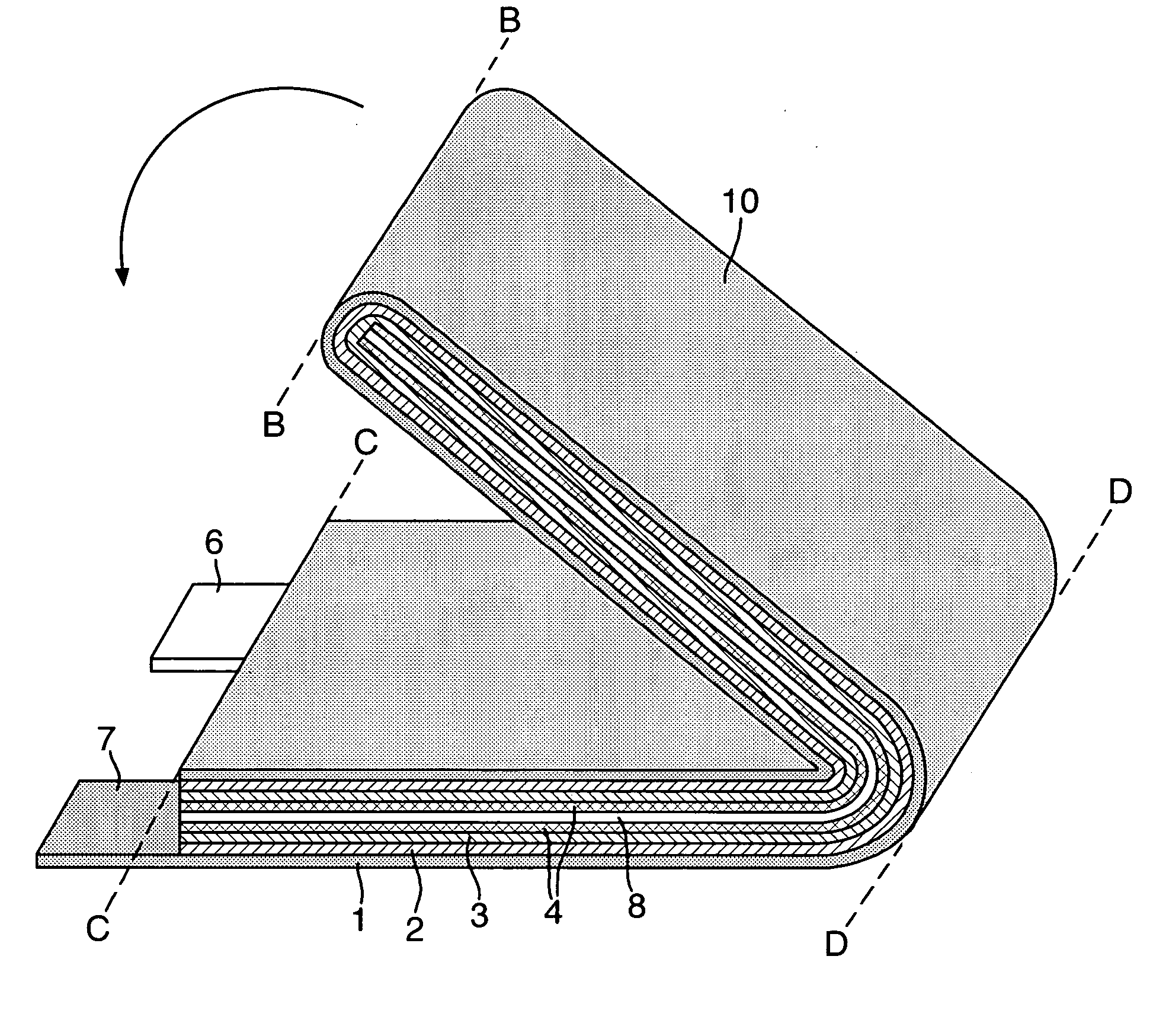
[0011] The use of parallel folds is convenient in rapidly reducing cell size and appears to lead to improved cell performance, for example, the utilisation of cell materials appears to be better. This is believed to be due to the fact that most of the folds are less acute than in prior art folding arrangements. Other advantages of having all the folds parallel to one another include ease of electrolyte filling, and reduced resistance to subsequent folding.
[0016] The loading of the cathode material layer may be selected so that the cathode capacity / cm2 is about half that of the anode capacity / cm2. One advantage of having a reduced cathode capacity / cm2 is that the coating thickness required for the active cathode material is less than it otherwise would be, which gives better coating adhesion, particularly in the case of carbon monofluoride. Furthermore, decreasing the cathode coating thickness leads to a beneficial increase in the power output for the battery.
[0025] The parallel folds described above provide benefits when employed in any pouch battery constructions, including prior art batteries having an anode of substantially the same size as the cathode. Thus, in a further aspect of the present invention, there is provided a pouch battery in which cathode, separator and anode sheets have been respectively overlaid on one another to form a stacked structure, and the structure has been successively folded in half so that its length is halved at each fold, each fold being made upon the same side of the structure with the fold lines extending perpendicular to the original length.

Problems solved by technology

Moreover, pouch batteries do not offer optimum conditions for battery safety, particularly when attempts are made to scale them up.

Method used


Image

  • Electrode assembly
  • Electrode assembly
  • Electrode assembly

Examples


example

[0047] The following Example illustrates the invention: A 25 Ah primary lithium carbon monofluoride cell was manufactured in the following way:

[0048] A cathode sheet was prepared by, first, grinding and mixing intimately 42 g carbon monofluoride and 3.2 g of conductivity additive (carbon black). A binder solution was prepared by dissolving 4.8 g of polyvinylidene fluoride (PVDF) in N-methyl pyrollidinone. Then a paste was formed from the CFx mixture and the PVDF solution.

[0049] Aluminium foil (1050 Alloy, 25-30 micron) was cleaned and the cathode paste was coated onto the Al foil to a depth of 570 micron, so as to give a cathode capacity of 12.6 to 13.6 mAh / cm2. The sheet was then dried to give a final cathode composition by weight of 84:9.6:6.4 w / o CFx:PVDF:conductivity additive, and a final coating thickness of 185 micron.

[0050] The cathode sheet was cut to a length of 208 cm and a width of 9 cm, leaving an extra length for the terminal. The sheets were folded in half and vacuu...


PUM

PropertyMeasurementUnit
Lengthaaaaaaaaaa
Structureaaaaaaaaaa
Sizeaaaaaaaaaa

Abstract

An electrode assembly is formed by respectively overlaying a sheet cathode 1, a sheet separator 3 and a double-sided sheet anode 8 to form a stacked structure 10, and subjecting the stacked structure to multiple folds, wherein the initial fold comprises folding the cathode in half around the double-sided anode so as to surround the respective upper and lower active anode surfaces thereof. The multiple folds may comprise one or more subsequent parallel folds made with the fold line D-D extending perpendicular to the original length of the stacked structure such that its overall length is halved at each fold. A pouch battery comprising said electrode assembly has improved safety and performance characteristics. The pouch battery construction has especial application to lithium primary batteries.

Description

FIELD OF THE INVENTION [0001] The present invention relates to pouch batteries and methods for their construction, and particularly to lithium primary batteries, such as, for example, lithium / carbon monofluoride batteries. BACKGROUND OF THE INVENTION [0002] So-called ‘pouch’ batteries, which are also known as ‘envelope’ or ‘packet’ batteries, are increasingly replacing traditional hard-cased batteries in portable electrical applications. In a typical pouch battery, the battery components are overlaid to form a laminated cell structure, folded to a required size and then packaged in a heat-sealable foil. This packaging method offers a light-weight and flexible solution to battery design, and is capable of achieving high energy densities, with the final capacity of the cell being selected according to the desired application. [0003] Pouch batteries can be based on a variety of different cell chemistries, and a range of electrolyte types can be utilised. Lithium primary and secondary b...

Claims


Application Information

Patent Timeline
IPC IPC(8): H01M4/58H01M6/10H01M6/16H01M6/50H01M10/04H01M10/052H01M10/0583H01M10/36H01M10/42H01M50/105H01M50/463
CPCH01M2/0207H01M2/1673H01M2/18H01M4/5835H01M6/10H01M10/0431Y10T29/4911H01M10/0583H01M10/4235H01M2200/00H01M2200/10H01M2300/0085H01M10/052Y02E60/10H01M50/46H01M50/463Y02P70/50H01M50/105
Inventor BOWLES, PETER G.EWEKA, EMMANUEL I.GIWA, CYRIL O.RITCHIE, ANDREW G.
Owner QINETIQ LTD
Learn More