Wraparound canceller, relay system, and wraparound cancelling method

a loop interference canceller and relay technology, applied in the field can solve the problems of deteriorating requiring new frequency resources to be secured, and using optical fibers has a problem of channel cost, so as to speed up the adaptive operation of loop interference cancellers, reduce the number, and improve the quality of relay signals.

Active Publication Date: 2005-09-01
PANASONIC CORP
View PDF5 Cites 18 Cited by
  • Summary
  • Abstract
  • Description
  • Claims
  • Application Information

AI Technical Summary

Benefits of technology

[0046] It is an object of the present invention to speed up an adaptive operation of a loop interference canceller by reducing the number of data pieces processed to thereby realize high trackability with respect to time variations of the phase

Problems solved by technology

However, the method using optical fibers has a problem of channel cost and the method using microwave requires new frequency resources to be secured.
Realizing a broadcast wave relay SFN involves the possibility of causing deterioration of the quality of the relay signal and problems of oscillation, etc., of an amplifier because of a phenomenon of radio waves emitted from a transmission antenna wrapping around a reception antenna.
However, since there are various situations of mountains and buildings and sufficient suppression of loop interference cannot be expected from measures like improvement of directional characteristics of antennas alone, it is effective to use a loop interference canceller using the signal processing technology in (3) in addition to the measures in (1) and (2).
However, from the standpoint of accuracy and stability, the impulse response cannot b

Method used


Image

  • Wraparound canceller, relay system, and wraparound cancelling method
  • Wraparound canceller, relay system, and wraparound cancelling method
  • Wraparound canceller, relay system, and wraparound cancelling method

Examples


Embodiment Construction

[0061] With reference now to the attached drawings, embodiments of the present invention will be explained in detail below.

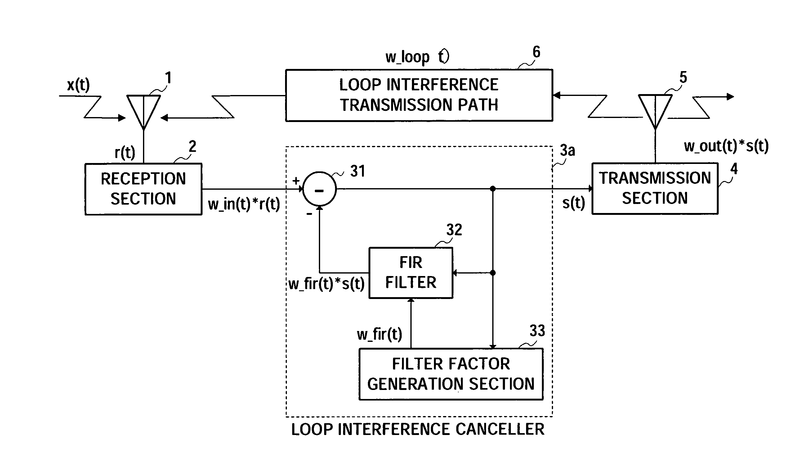
[0062]FIG. 5 is a block diagram showing a model of an SFN relay system using a loop interference canceller. Symbol “*” in the figure denotes a convolutional calculation. Furthermore, signals or responses will be handled as complex numbers hereafter unless otherwise specified. Suppose “(t)” denotes a signal in the time domain and “(ω)” denotes a signal in the frequency domain, and when a signal is defined in one domain, it is also defined in the other domain simultaneously.

[0063] The reception section 2 in FIG. 5 converts a signal in an RF (Radio Frequency) band to a baseband signal, while the transmission section 4 contrarily converts a baseband signal to an RF band signal. However, these frequency conversions do not have any substantial influence on the present invention, and therefore these frequency conversions will not be mentioned hereafter unless otherwi...


PUM


Abstract

A loop interference canceller that carries out an adaptive operation of responding to time variations of the phase or level of loop interference wave or key station wave at high speed and with high accuracy and reduces the size of an apparatus. The loop interference canceller of the present invention limits the number of data pieces of the transmission path characteristic estimation section, realizes expansion to the entire band not through interpolation but through 0 insertion in a frequency domain and windowing after time domain transformation to reduce the number of data pieces processed and speed up the adaptive operation of the loop interference canceller, and can thereby realize high trackability for time variations of the phase and level of loop interference wave or key station wave, increase the accuracy of processing inside, perform high accuracy cancellation operation, reduce the circuit scale and achieve an advantageous effect of realizing miniaturization of the apparatus.

Description

TECHNICAL FIELD [0001] The present invention relates to a loop interference canceller which cancels loop interference using a transmission path characteristic estimated from an OFDM (Orthogonal Frequency Division Multiplexing) signal, and more particularly, to a loop interference canceller, relay system and loop interference canceling method which speeds up an adaptive operation of the loop interference canceller by reducing the number of processed data pieces, realizes high trackability with respect to time variations of the phase and level of a loop interference wave and key station wave, carries out internal processing at a higher degree of accuracy, and can thereby carry out high accuracy cancellation operation and realize miniaturization of the apparatus with a reduced circuit scale. BACKGROUND ART [0002] In carrying out broadcast wave relay SFN (Single Frequency Network), for example, in terrestrial digital broadcasting, use of an OFDM transmission scheme is under study in rec...

Claims


Application Information

Patent Timeline
IPC IPC(8): H04B3/23H03H17/04H04B7/015H04B7/155H04H20/00H04H20/06H04H20/67H04J11/00
CPCH04B3/23H04B7/15585H04H20/06H04L25/0232H04L5/0048H04L25/0204H04H20/67
Inventor KUNIEDA, YOSHINORIYOMO, HIDEKUNIKAWAI, YOSHIHITOHAYASHI, KENICHIROSUZUKI, KAZUAKI
Owner PANASONIC CORP
Why Eureka
Try Eureka