Computer simulator for continuously variable transmissions

a computer simulator and transmission technology, applied in the direction of instruments, configuration cad, gearing, etc., can solve the problems of significant time and cost expenditure, difficult to etc., to accurately predict or analyze the durability of the v-belt system

Inactive Publication Date: 2005-09-01
HONDA MOTOR CO LTD
View PDF3 Cites 20 Cited by
  • Summary
  • Abstract
  • Description
  • Claims
  • Application Information

AI Technical Summary

Benefits of technology

[0007] The object of the present invention is solve the drawbacks of the prior art and to provide a computer simulator for CVTs that improves upon the existing computer simulator by performing a transient simulation to arrive at a true dynamic balance of the block, ring, and pulley forces, while utilizing the actual block and ring geometry in calculating ring bending forces, and including a technique for maintaining a desired speed ratio of the V-belt system, thereby allowing the user to accurately predict or analyze the durability of the V-belt system.

Problems solved by technology

The design process for developing a CVT V-belt system requires a number of physical prototypes of the CVT V-belt system, requiring significant expenditures of time and costs.
Also, this existing simulation does not utilize the actual block and ring geometry in calculating ring bending forces and torques, and does not include a technique for maintaining a desired speed ratio of the belt, thereby rendering it difficult to predict or analyze the durability of the V-belt system.

Method used


Image

  • Computer simulator for continuously variable transmissions
  • Computer simulator for continuously variable transmissions
  • Computer simulator for continuously variable transmissions

Examples


Embodiment Construction

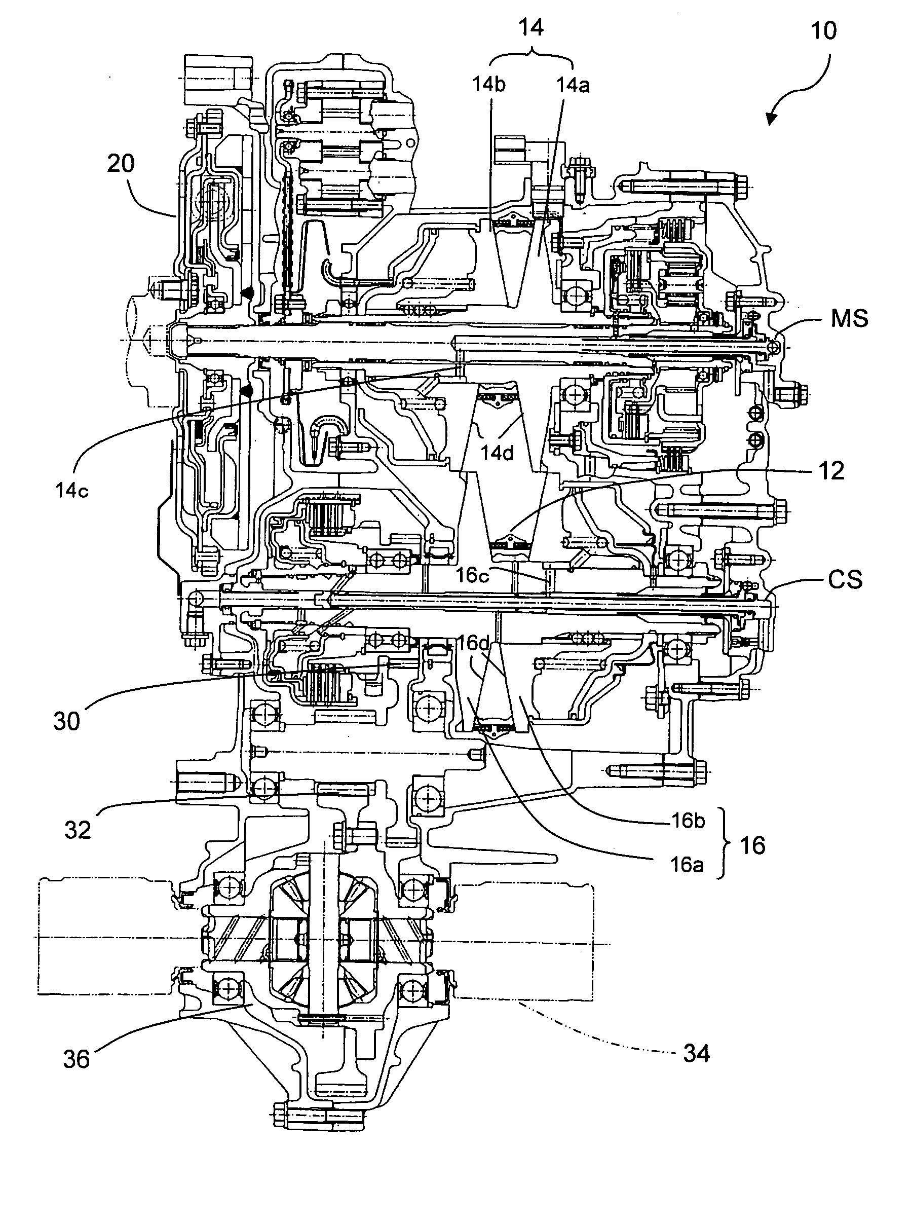
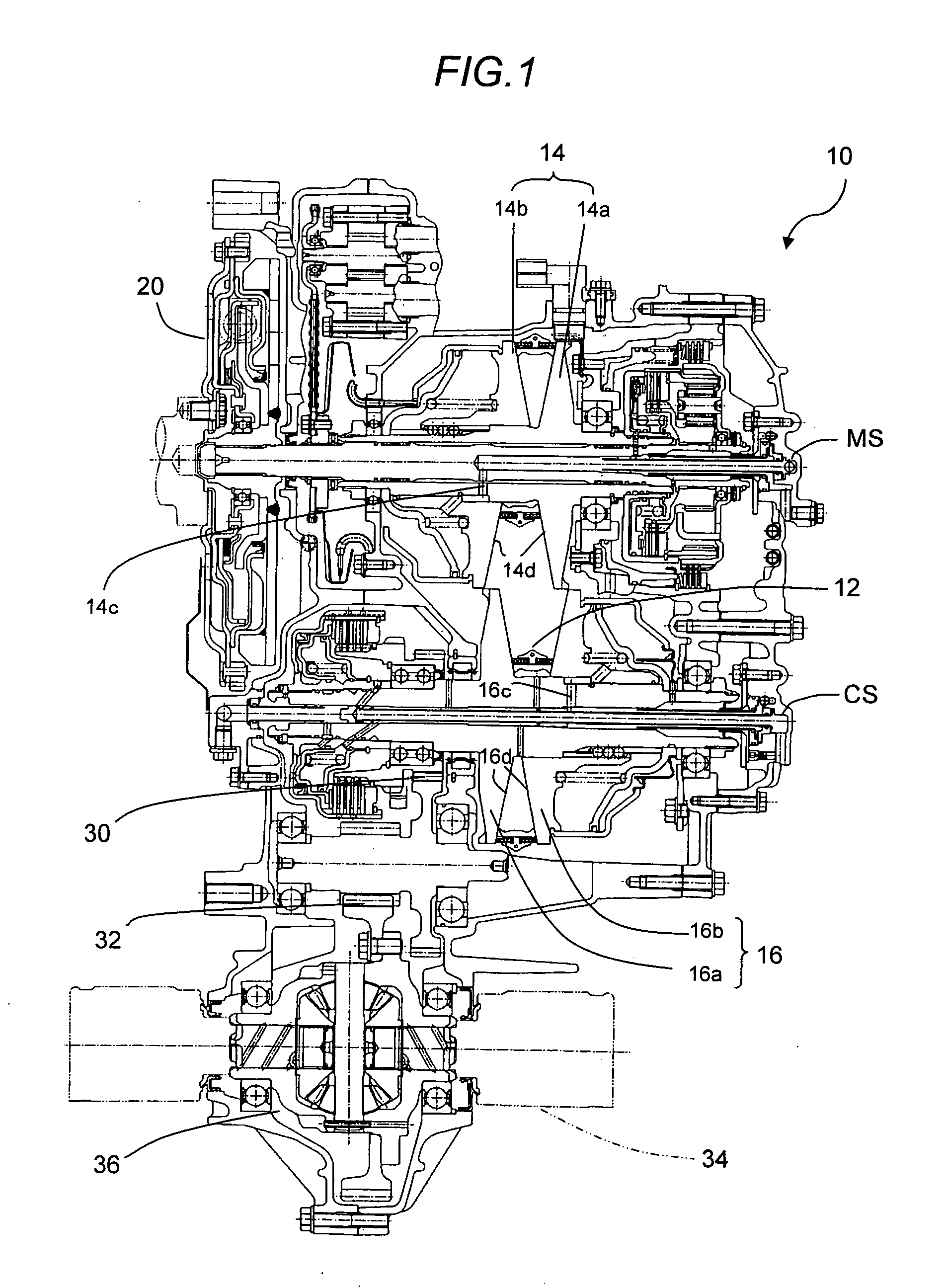
[0023]FIG. 1 is an overall cross-sectional a V-belt system of a continuously variable transmission (hereinafter simply referred to as the “CVT”) to which a computer simulator for CVTs according to the embodiment is applied.

[0024] In the figure, reference numeral 10 indicates a CVT having a metal-pushing V-belt 12. The V-belt 12 is wound around pulleys 14, 16 that are fixed on a main shaft (transmission input shaft) MS connected to a crankshaft (not shown) of the internal combustion engine through a flywheel 20 having a dumper mechanism, and on a countershaft (transmission output shaft) CS provided in parallel with the main shaft MS to be mounted on a vehicle (not shown)

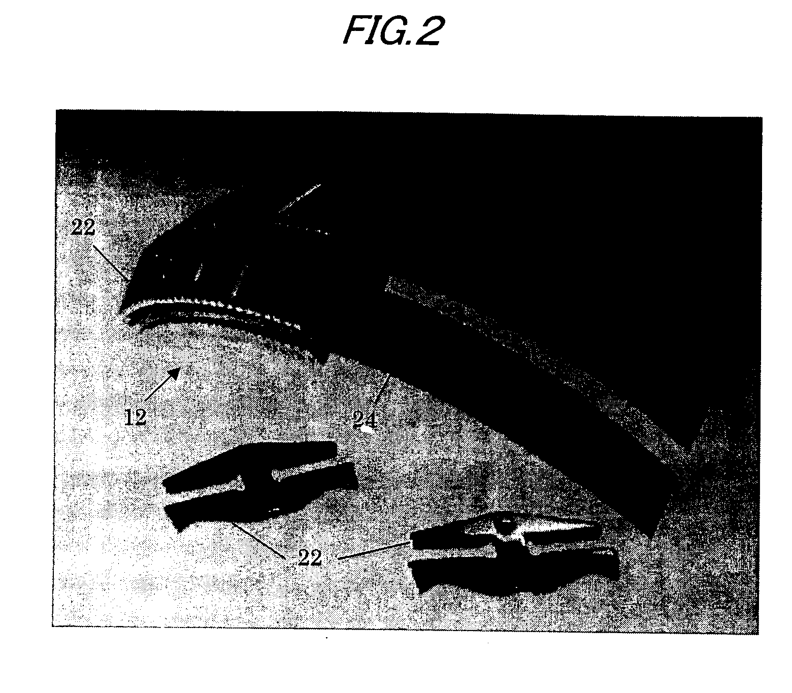
[0025]FIG. 2 is a photograph showing the V-belt 12 in detail. As shown in FIG. 2, the V-belt 12 includes a plurality of, i.e., 428 V-shaped blocks 22 (hereinafter collectively referred to the “block”) and a ring 24 made of a plurality of, i.e., two rows of 12 bands. The V-belt 12 are each made of a thin metal plate ...


PUM


Abstract

Improvements are made to a multi-body simulation (MBS) for computing belt dynamics in metal pushing V-Belts for CVTs. All of the improvements combine to more accurately model the forces in the CVT mechanism, and also provide insight into the mechanism performance. One improvement more accurately captures effects of ring bending, using ring and block gap geometry to calculate bending forces and torques. A second improvement is implementation of a thrust controller to adjust pulley thrust to control CVT input/output speed ratio. Pulley thrust is adjusted by means of a feedback loop until a desired speed ratio is obtained. Finally, pulley conical (tilt) deflection is modeled using a stiffness representation that is a function of the block radius on the pulley face.

Description

BACKGROUND OF THE INVENTION [0001] 1. Field of the Invention [0002] The present invention relates to a computer simulator for continuously variable transmissions (CVTs), more particular to a computer simulator for analyzing dynamics in metal pushing V-belt systems for vehicle CVTs to predict or analyze the durability of the V-belt systems. [0003] 2. Description of the Related Art [0004] The design process for developing a CVT V-belt system requires a number of physical prototypes of the CVT V-belt system, requiring significant expenditures of time and costs. For that reason, simulation is used to test potential designs and reduce the number of physical prototypes needed. The simulation allows modeling of design innovations, and identifies promising directions for design improvement. [0005] As a tool for mechanism analysis, multi-body computer simulation has been well known. For example, the multi-body computer simulation of a CVT V-belt is described in U.S. Pat. No. 6,568,280, where...

Claims


Application Information

Patent Timeline
Patent Type & Authority Applications(United States)
IPC IPC(8): F16H9/12F16H9/18G06F17/50G06G7/48
CPCF16H9/18G06F17/5009G06F2217/02G06F17/5095G06F17/5086G06F2111/20G06F30/15G06F30/17G06F30/20G06F30/23
Inventor LEWIS, ALAN D.SAITO, TOSHIHIRO
Owner HONDA MOTOR CO LTD
Why Eureka
Try Eureka