Method and apparatus for serial array excitation for high field magnetic resonance imaging

a high-field magnetic resonance and serial array technology, applied in the field of serial array excitation for high-field magnetic resonance imaging, can solve the problems of poor homogeneity of transmit excitation in magnetic resonance imaging (mri) for samples the size of human torsos, inability to create the needed independence, and standard mri methods extended to this short wavelength regime have produced undesirable results

Inactive Publication Date: 2005-09-08
INVIVO CORP
View PDF7 Cites 4 Cited by
  • Summary
  • Abstract
  • Description
  • Claims
  • Application Information

AI Technical Summary

Problems solved by technology

Accordingly, at magnetic field strengths of, for example, 3T and above, the homogeneity of transmit excitation in magnetic resonance imaging (MRI) is poor for samples the size of the human torso.
The result has been that standard MRI methods extended to this short wavelength regime have produced undesirable outcomes (Collins et al., Magn Reson Med, 40: 847-856 (1998); Hoult et al., Magn Reson Imaging, 12: 46-67 (2000); Ibrahim et al, Magn Reson Imaging, 19: 219-226 (2001);

Method used


Image

  • Method and apparatus for serial array excitation for high field magnetic resonance imaging
  • Method and apparatus for serial array excitation for high field magnetic resonance imaging
  • Method and apparatus for serial array excitation for high field magnetic resonance imaging

Examples


example 1

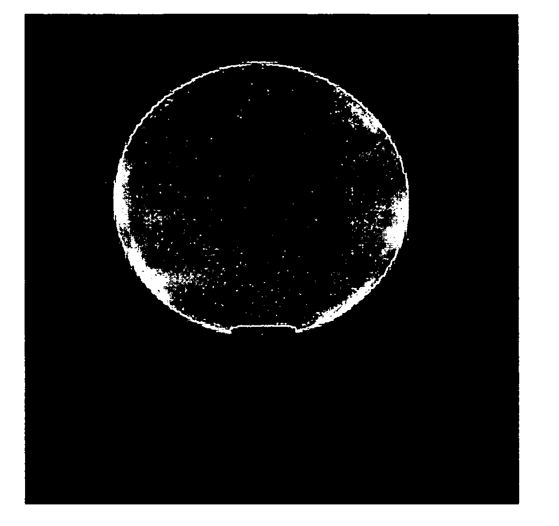
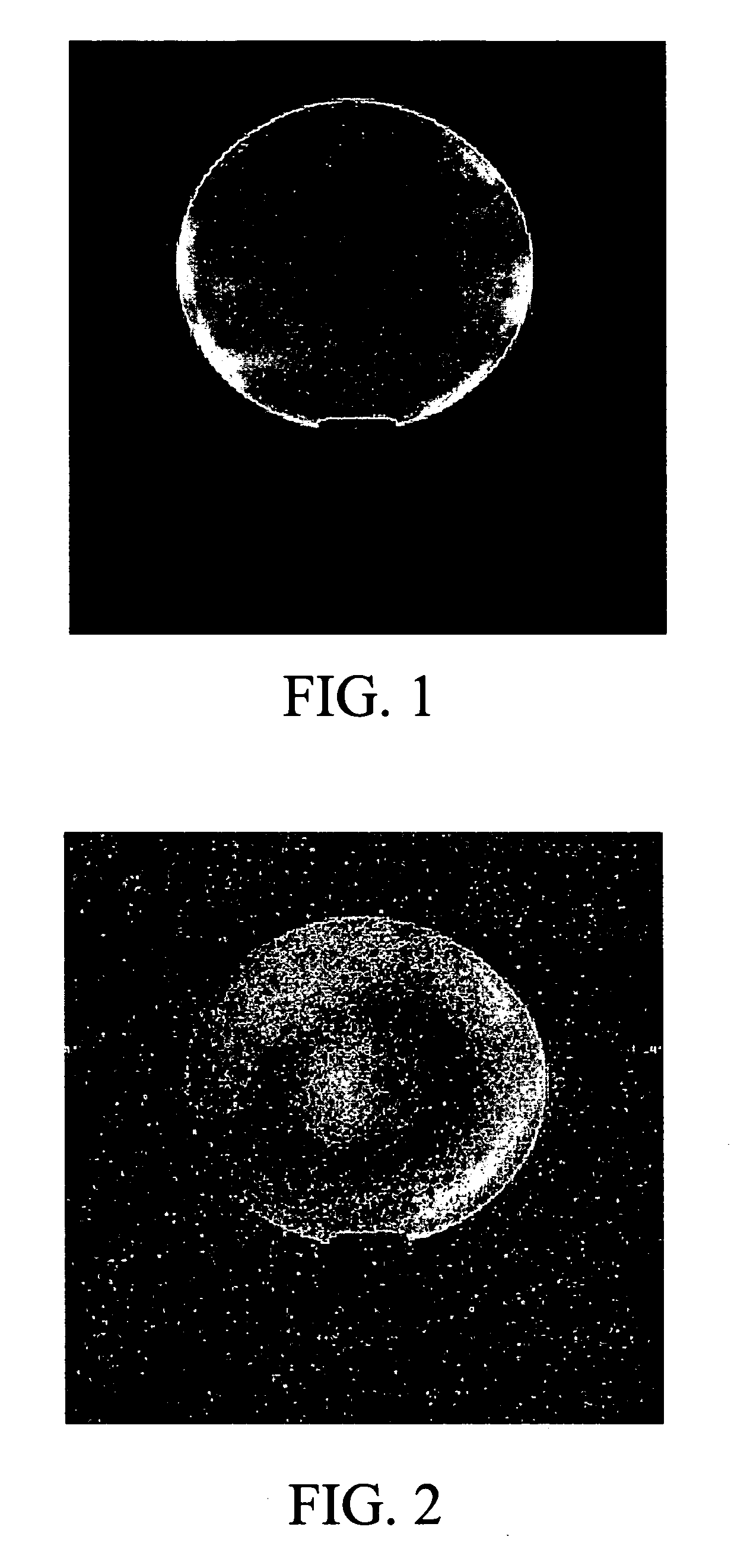
[0035] A two-loop coil with canceling currents was tuned to 470 MHz. Adjustments were made in the simulator. The sensitivity profile was much “flatter” than a conventional surface coil and, therefore, it had better flip angles at depths within the field of view. A 2 liter bottle with brain equivalent solution was used as a phantom to take 8 images. Each image was made with the coil at a different location around the phantom, by rotating (by hand), the coil approximately 45 degrees between each image. The 8 images were added using a spectrometer, and a sum-of-squares reconstruction was performed as shown in FIG. 1.

example 2

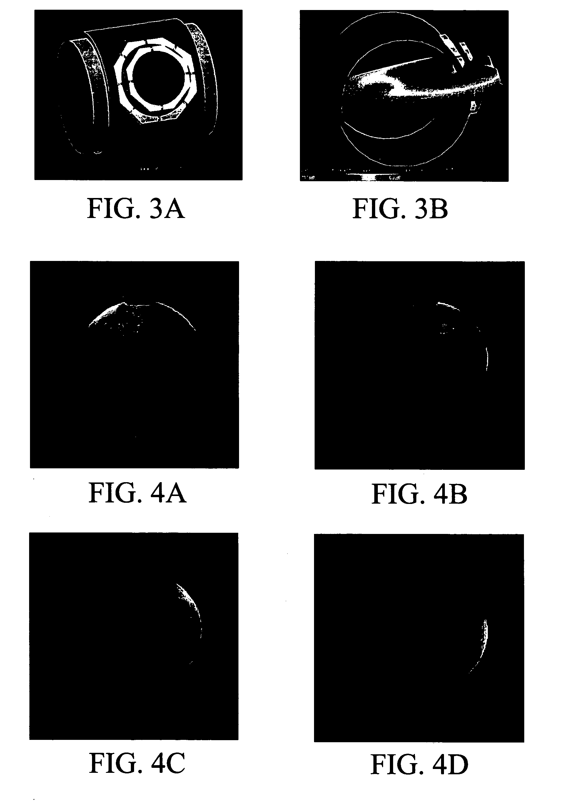
[0036] In this experiment, a local field was produced that did not excite modal behavior across the entire volume, but had a field at the center of the volume that was of the same order of magnitude as the field at the surface of the volume. An optimized CRC coil was chosen for this purpose (Vaughan et al., Magn Reson Med, 46: 24-30 (2001); Beck et al., Magn Reson Med, 51: 1103-1107 (2004)). The CRC coil was placed on an acrylic cylinder having a 15.3 cm (6″) outer diameter. The outer loop had a diameter of 9 cm and the inner loop 6 cm. The inner loop was displaced vertically by 0.5 cm. The geometry is shown in FIG. 3A. The CRC was loaded with a large cylindrical phantom (2L bottle, diameter 12 cm, height 20 cm) containing a tissue equivalent solution (ε=48.6, σ=0.6 S / m @470 MHz). The CRC was simulated using Remcom's XFDTD, a finite difference time domain electromagnetic field simulator. The Yee-cell was 1 mm on a side, the simulation space 180×195×240 cells, and 20,000 time-steps o...


PUM


Abstract

The subject invention pertains to methods and apparatus for producing excitation for magnetic resonance imaging (MRI) from a plurality of local exciting elements such that each local exciting element's excitation is independent of the other local exciting elements' excitation. The methods and apparatus of the subject invention can be utilized in magnetic resonance imaging (MRI) and in magnetic resonance spectroscopy (MRS), where MRI produces a magnitude for each pixel that combines many frequency components, typically for magnitude images, and MRS produces a spectrum of outputs over a range of frequencies for each pixel, typically a spectral output. The subject method and apparatus can be utilized for exciting proton, and/or other imaging materials relating to spin magnetization, such as, but not limited to, phosphorous, carbon, and fluorine. In a specific embodiment, the subject invention achieves the independence of the local exciting elements' excitations via serial means, such that excitation is produced by each local exciting element at a different time than the other local exiting elements.

Description

CROSS-REFERENCE TO RELATED APPLICATION(S) [0001] The present application claims benefit of U.S. provisional patent application Ser. No. 60 / 550,875, filed Mar. 5, 2004, which is hereby incorporated by reference herein in its entirety, including any figures, tables, or drawings.BACKGROUND OF INVENTION [0002] Because of the trend towards higher attainable signal-to-noise ratio (SNR) with increasing magnetic field strength in Magnetic Resonance Imaging (MRI), magnet field strengths have increased to 9.4 Tesla state-of-the-art human research systems, and considerably higher for small animal systems. As the field strength increases, the Larmor frequency of the spin precession increases linearly with the relationship f(MHz)=42.6 MHz / Tesla. For MRI systems operated at approximately 3 Tesla (T), or above, the Larmor frequency is associated with wavelengths in the biological sample that are shorter than objects to be imaged. Accordingly, at magnetic field strengths of, for example, 3T and abo...

Claims


Application Information

Patent Timeline
IPC IPC(8): G01R33/3415G01R33/561G01V3/00
CPCG01R33/3415G01R33/5659G01R33/5611
Inventor DUENSING, G. RANDY
Owner INVIVO CORP
Why Eureka
Try Eureka