
Display device

Inactive Publication Date: 2005-09-08
HITACHI DISPLAYS
View PDF12 Cites 30 Cited by
  • Summary
  • Abstract
  • Description
  • Claims
  • Application Information

AI Technical Summary

Benefits of technology

[0026] According to the present invention, it is possible to elongate the effective optical length by reducing the thickness of the direct backlight unit, and, hence, it is possible to largely enhance the in-plane brightness and the chromaticity distribution, thus exhibiting a high color reproducibility. Further, it is also possible to obtain excellent advantageous effects, such as a high brightness display with a rapid response speed.
[0027] Further, according to the present invention, it is possible to obtain an extremely excellent advantageous effect, such as an equivalent or superior in-plane brightness, and an enhanced chromaticity distribution, compared to the cold cathode fluorescent lamp which uses mercury, and the use of the mercury-free direct backlight unit for a large-sized display device is friendly to the environment.BRIEF DESCRIPTION OF THE SEVERAL VIEWS OF THE DRAWING
[0028]FIG. 1 is a diagram which illustrates the constitution of an embodiment 1 of a liquid crystal display device having a direct LED backlight unit as the illumination source of a display device according to the present invention;
[0029]FIG. 2 is an enlarged plan view showing the planar structure of the liquid crystal display device shown in FIG. 1 as viewed from the A-A′ line direction;
[0030]FIG. 3 is an enlarged cross-sectional view showing the positional relationship between a disc-like light diffusion plate and an LED chip;
[0031]FIG. 4(a) is a side view and FIG. 4(b) is a developed perspective view illustrating the constitution of the liquid crystal display device shown in FIG. 1;

Problems solved by technology

On the other hand, a coupling loss is generated between respective kinds of optical members which are present between the optical paths, and, hence, only approximately 50 to 60% of the light emitted from the light emitting diode array LEDA is irradiated to the liquid crystal display panel PNL from the surface of the optical compensation sheet stacked body OPS, thus giving rise to a drawback in that the utilization efficiency of the light source light is low.
With respect to the direct backlight unit, an attempt to ensure that there will be a prolonged optical path by using the usual means to enhance the degree of color mixing increases the thickness of the whole backlight unit, and, hence, the use of a direct backlight is not practical.
Accordingly, there has been a drawback in that the direct backlight unit cannot produce a subjective evaluation equal to or superior to the subjective evaluation given to the current backlight unit which uses a cold cathode fluorescent lamp.

Method used


Image

  • Display device
  • Display device
  • Display device

Examples


embodiment 1

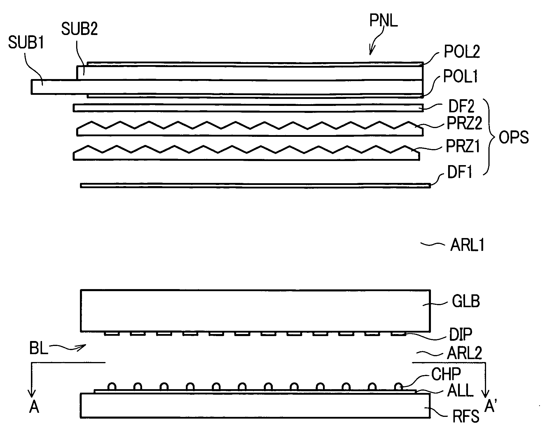
[0039]FIG. 1 and FIG. 2 show the constitution of an embodiment 1 of a liquid crystal display device having a direct LED backlight unit. In FIG. 1, reference designation PNL indicates a liquid crystal display panel. In this liquid crystal display panel PNL, a liquid crystal layer LC is sandwiched between a first substrate SUB1 and a second substrate SUB2, formed of a glass plate and having pixels formed on inner surfaces thereof. A first polarizer POLL is laminated to a first main surface (backlight device side) and a second polarizer POL2 is laminated to a second main surface (display surface side) by adhesion.

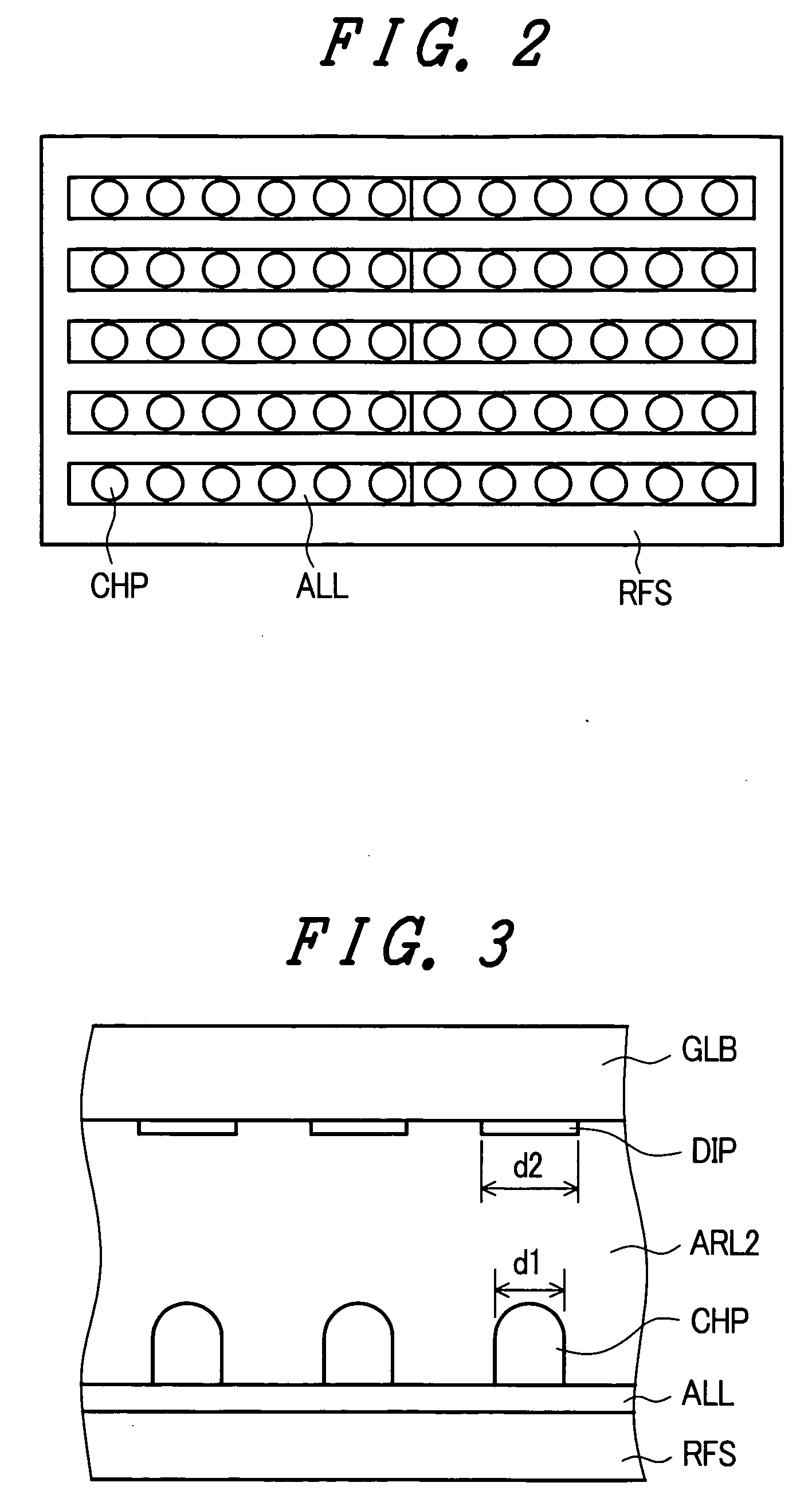
[0040] Further, on a back surface side of the liquid crystal display panel PNL, an optical compensation stacked sheet OPS is arranged. On a back surface side of the optical compensation stacked sheet OPS, a light guide plate GLB, formed of a transparent acrylic resin material, is arranged by way of a first air layer ARL1. On a back surface of the light guide plate GLB, a plur...

embodiment 2

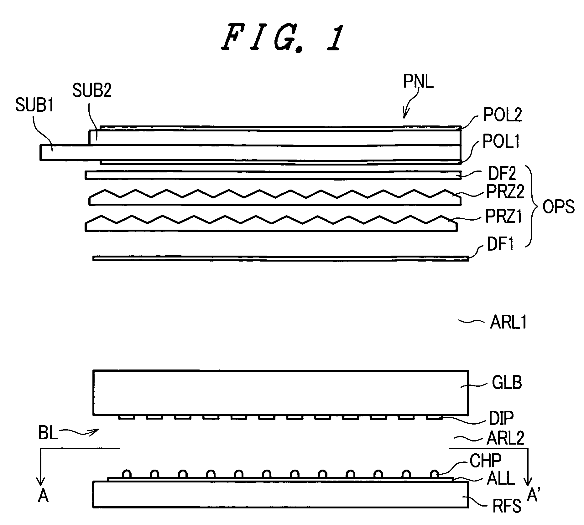
[0059]FIG. 6(a) and FIG. 6(b) show an embodiment 2 of the liquid crystal display device which is provided with a back direct type LED backlight unit according to the present invention. In the drawing, parts having identical functions with parts in FIG. 1 are given the same symbols, and a repeated explanation thereof will be omitted. The constitution of FIG. 6(a) and FIG. 6(b) differs from the constitution of FIG. 1 in that the disc-like light diffusion plate DIP of embodiment 1 is not mounted on the light incident surface of the light guide plate GLB; and, on the portion of the light incident surface which faces to the optical compensation sheet stacked body OPS, a planar light diffusion sheet DF3 is fixed by adhesion or the like.

[0060] In such a constitution, by changing the position of the planar light diffusion sheet DF3 mounted on the light incident surface of the light guide plate GLB, focusing on the changes of the brightness, the brightness distribution and the chromaticity ...


PUM


Abstract

A display device includes an optical compensation sheet stacked body mounted on a back surface of a liquid crystal display panel, and a light guide plate mounted on a back surface of the optical compensation sheet stacked body. A first air layer is interposed between the optical compensation sheet stacked body and the light emitting surface of the light guide plate, and a plurality of diffusion plates are mounted on the light incident surface of the light guide plate. A reflection sheet is arranged to face the light guide plate, and an array of an LED chips is provided on a front surface of the reflection sheet. A second air layer is interposed between the light diffusion plates and the LED array. Light from the LED chips having a plurality of colors is mixed and effective optical path length can be prolonged, whereby the least coupling loss is obtained.

Description

BACKGROUND OF THE INVENTION [0001] The present invention relates in general to a display device; and, more particularly, the invention relates to a solid-light-emitting element (LED) direct backlight unit, which is mounted on a back surface of a liquid crystal display panel and is represented by a light emitting diode which irradiates light to the liquid crystal display panel. [0002] Recently, a liquid crystal display device which is light-weight and exhibits a low power consumption has been popularly used. This liquid crystal display device is constituted of a liquid crystal display panel in which a liquid crystal layer is sandwiched between a pair of insulating substrates, wherein at least one of the insulating substrates is preferably made of glass. The liquid crystal display panel has electrodes for selecting pixels, or active elements, such as thin film transistors, on an inner surface / inner surfaces of one or both insulating substrates thereof, whereby electronic latent images...

Claims


Application Information

Patent Timeline
IPC IPC(8): F21V8/00F21Y101/02G02B6/00G02F1/1335G02F1/13357
CPCG02F1/133603
Inventor KOGANEZAWA, NOBUYUKITOKUYAMA, HIROSHITOBE, AKIYOSHI
Owner HITACHI DISPLAYS
Features
  • Generate Ideas
  • Intellectual Property
  • Life Sciences
  • Materials
  • Tech Scout
  • Unparalleled Data Quality
  • Higher Quality Content
  • 60% Fewer Hallucinations
Learn More