
Imaging system with large depth of field

Inactive Publication Date: 2005-09-08
AGILENT TECH INC
View PDF5 Cites 10 Cited by
  • Summary
  • Abstract
  • Description
  • Claims
  • Application Information

AI Technical Summary

Benefits of technology

[0006] In accordance with the invention, an optical imaging system and method is provided for achieving a large depth of field without having to decrease the relative aperture of an imaging lens.

Problems solved by technology

Decreasing the relative aperture, however, reduces light sensitivity and resolution; and, as a result, it is difficult to design an imaging system that has a large depth of field while maintaining high light sensitivity and fine resolution.

Method used


Image

  • Imaging system with large depth of field
  • Imaging system with large depth of field

Examples


Embodiment Construction

[0010] Embodiments in accordance with the invention provide an imaging system and method for achieving a large depth of field without having to decrease the relative aperture of an imaging lens.

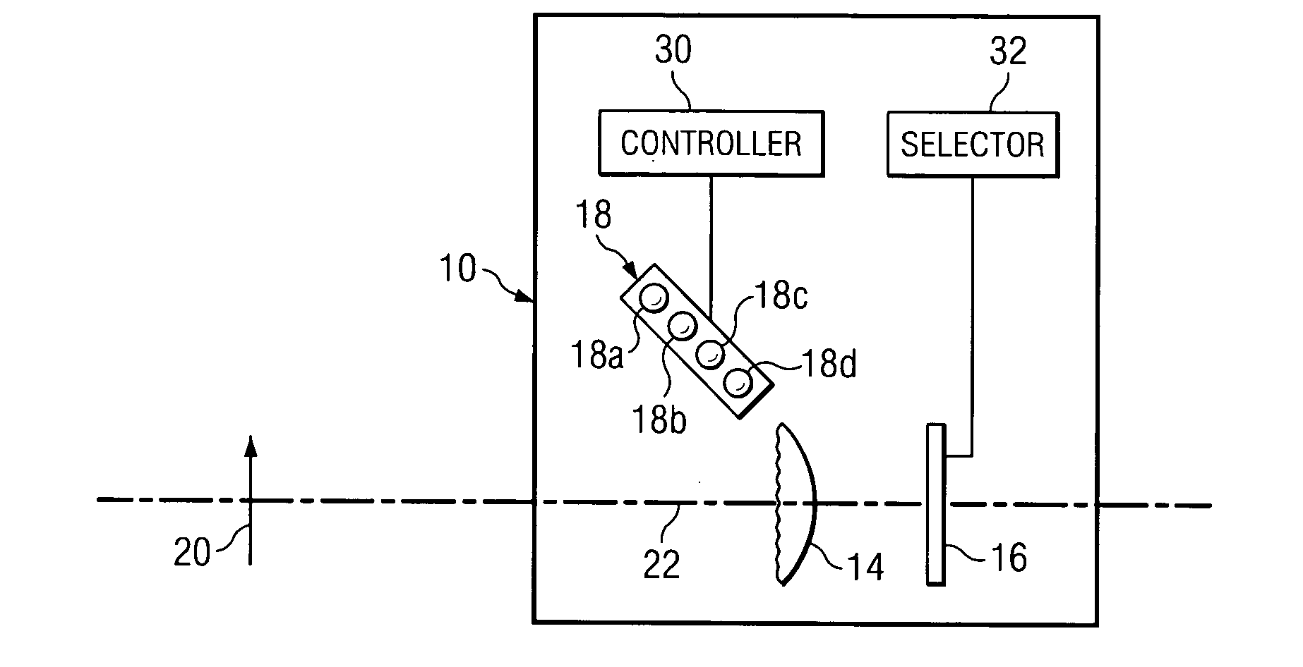
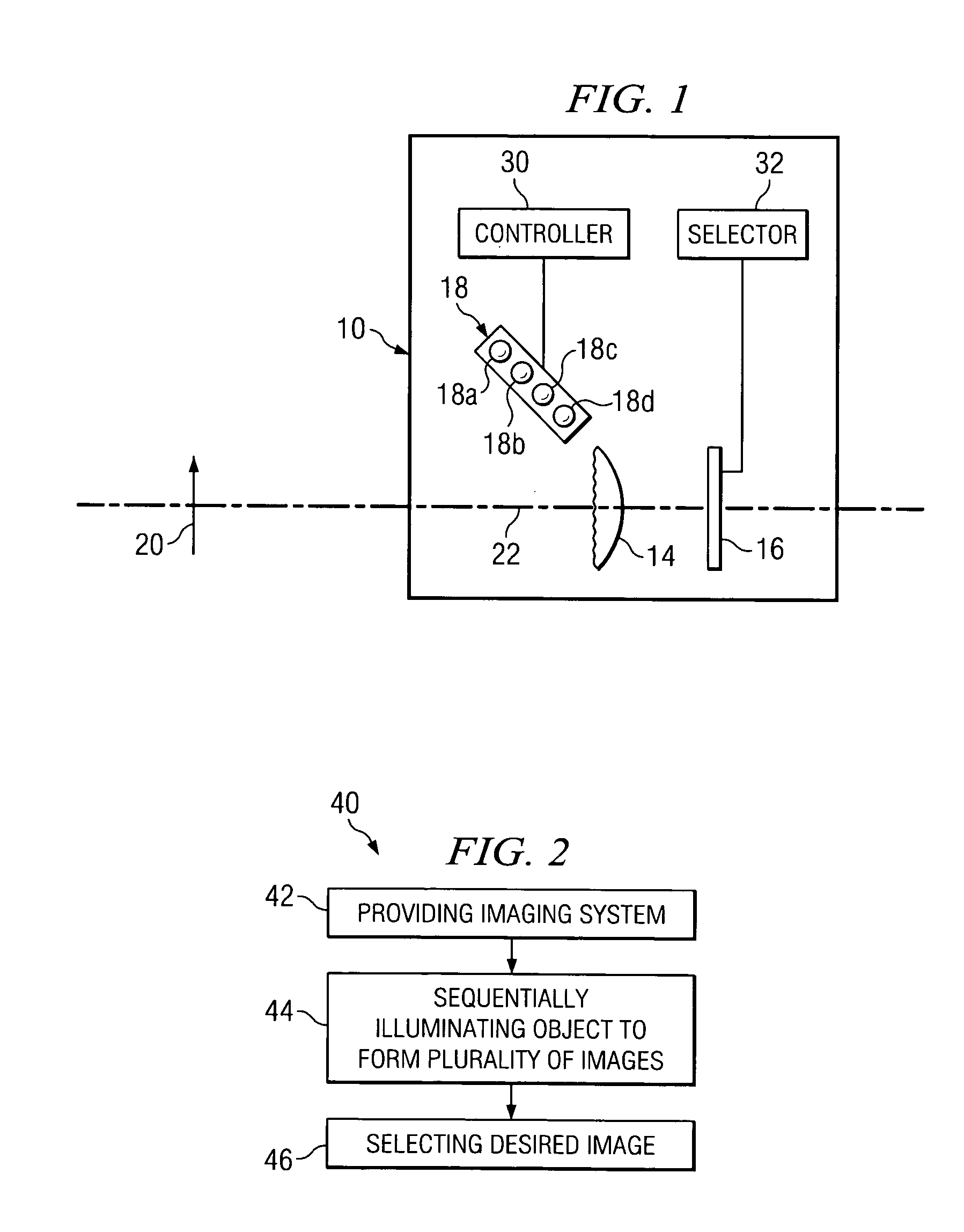
[0011]FIG. 1 schematically illustrates an imaging system according to an exemplary embodiment in accordance with the invention. The system is generally designated by reference number 10 and has imaging lens 14 for forming an image of an object 20, image receiving unit 16 for receiving the image formed by imaging lens 14, and light source 18 for illuminating object 20 during an image forming operation. In the exemplary embodiment illustrated in FIG. 1, imaging system 10 is a digital camera, for example, a digital still camera; however, the invention is not limited to any particular type of camera. Also, in the exemplary embodiment illustrated in FIG. 1, light source 18 is incorporated in the camera, however, light source 18 and the camera can also be separate components of imaging system 10. ...


PUM


Abstract

An optical imaging system and method for achieving a large depth of field without decreasing the relative aperture of an imaging lens. The imaging system has a light source for sequentially illuminating an object to be imaged with light of different ones of a plurality of wavelengths, and an imaging lens that has a focal length that varies with the wavelength of the light that illuminates the object. For each wavelength of light by which the object is illuminated, the imaging lens will image a different object plane onto an image receiving unit, and the image receiving unit will capture one well-focused, high resolution image of the object.

Description

BACKGROUND OF THE INVENTION [0001] 1. Technical Field of the Invention [0002] The present invention relates generally to the field of imaging systems. More particularly, the invention relates to an imaging system and method for achieving a large depth of field without decreasing the relative aperture of an imaging lens. [0003] 2. Background of Invention [0004] A large depth of field is important in imaging systems having an imaging lens position that is fixed with respect to an image receiving surface, but in which the distance along the optical axis from the lens to the object to be imaged may vary significantly. In a typical imaging system, depth of field is inversely proportional to the relative aperture of the imaging lens such that the relative aperture of the lens must be decreased in order to increase the depth of field. Decreasing the relative aperture, however, reduces light sensitivity and resolution; and, as a result, it is difficult to design an imaging system that has a...

Claims


Application Information

Patent Timeline
IPC IPC(8): G02B21/06
CPCG01J3/10G01J2003/1282G01J3/32G01J3/18
Inventor GROT, ANNETTE C.VENKATESH, SHALINI
Owner AGILENT TECH INC
Learn More