Electro-optic mirror cell

Active Publication Date: 2005-09-08
DONNELLY CORP
View PDF99 Cites 298 Cited by
  • Summary
  • Abstract
  • Description
  • Claims
  • Application Information

AI Technical Summary

Benefits of technology

[0012] The sheet or sheets thus may form at least two reflective element assemblies or cells. Because the sheet is large enough to have two or more mirror shapes defined thereon, the sheet may be handled along its edges by the conveyor and/or operators and, thus, may be handled in an area that is outside of the pristine cell surfaces within the epoxy seals/mirror shapes. The handling or conveying of the sheet thus does not encroach the pristine surfaces and thus does not damage or harm the pristine surfaces during the manufacturing and assembling of the cells. The method of the present invention thus provides an enhanced manufacturing process that limits or substantially precludes touching or harming of the pristine surfaces of the mirror shapes during the cleaning, coating, conveying and adhering processes. Also, because the sheets are larger than the individual substrates, economies in the coating process may be realized, since multiple mirror shapes may be coated during one coating process and without individual fixturing of the mirror shapes.
[0013] The present invention also provides a means for masking a substrate during the coating process to provide a window in the metallic reflective coating on a third surface of a reflective element assembly. The mask may be retained in the appropriate position via magnetic attraction to a magnetic element on a substrate holding fixture, or may be held by a bridge or arm attached to and extending from the substrate holding fixture. Optionally, the mask fixture may comprise a bridge that is attached at opposite ends to the substrate holding fixture to provide a robust, substantially stable mask holding device. Optionally, the mask may be biased, such as by a resilient member or spring, to affirmatively engage the surface of the glass substrate that is positioned at the mask, such that the mask is urged into engagement with the surface of the substrate to provide a generally flush engagement of the mask to the substrate at the desired location, and thus to avoid accumulation of any deposited coating at the region of the substrate mask. The mask thus may be retained in the desired location when the substrates are placed in a holding fixture and then placed in a deposition chamber, such as a vacuum deposition chamber, such as for a sp

Problems solved by technology

Such contaminants (whether contacting the surfaces before or after coating) may interfere with the coloration/bleach mechanism and/or the coating durability/adhesion (such that voids may exist in the coating due to glass chips or the like), as well as affect the perimeter seal adhesion, and thus often result in a flawed cell exhibiting cosmetic defects that is often discarded or scrapped.
Difficulties in keeping the surfaces pristine are often encountered because the individual cut shape substrates are often handled and conveyed as they are moved from one process or station to the next.
If any marks or debris are left by the rollers, they may be visible in the finished product and ma

Method used


Image

  • Electro-optic mirror cell
  • Electro-optic mirror cell
  • Electro-optic mirror cell

Examples


Example

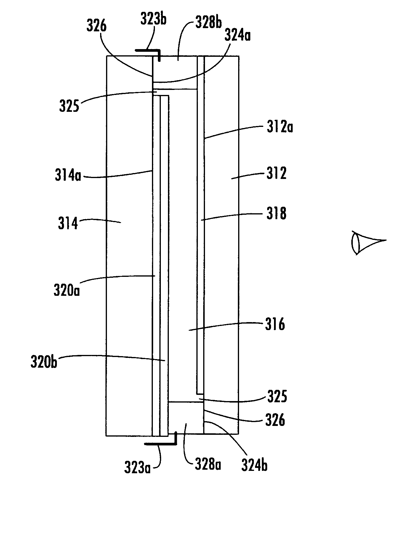
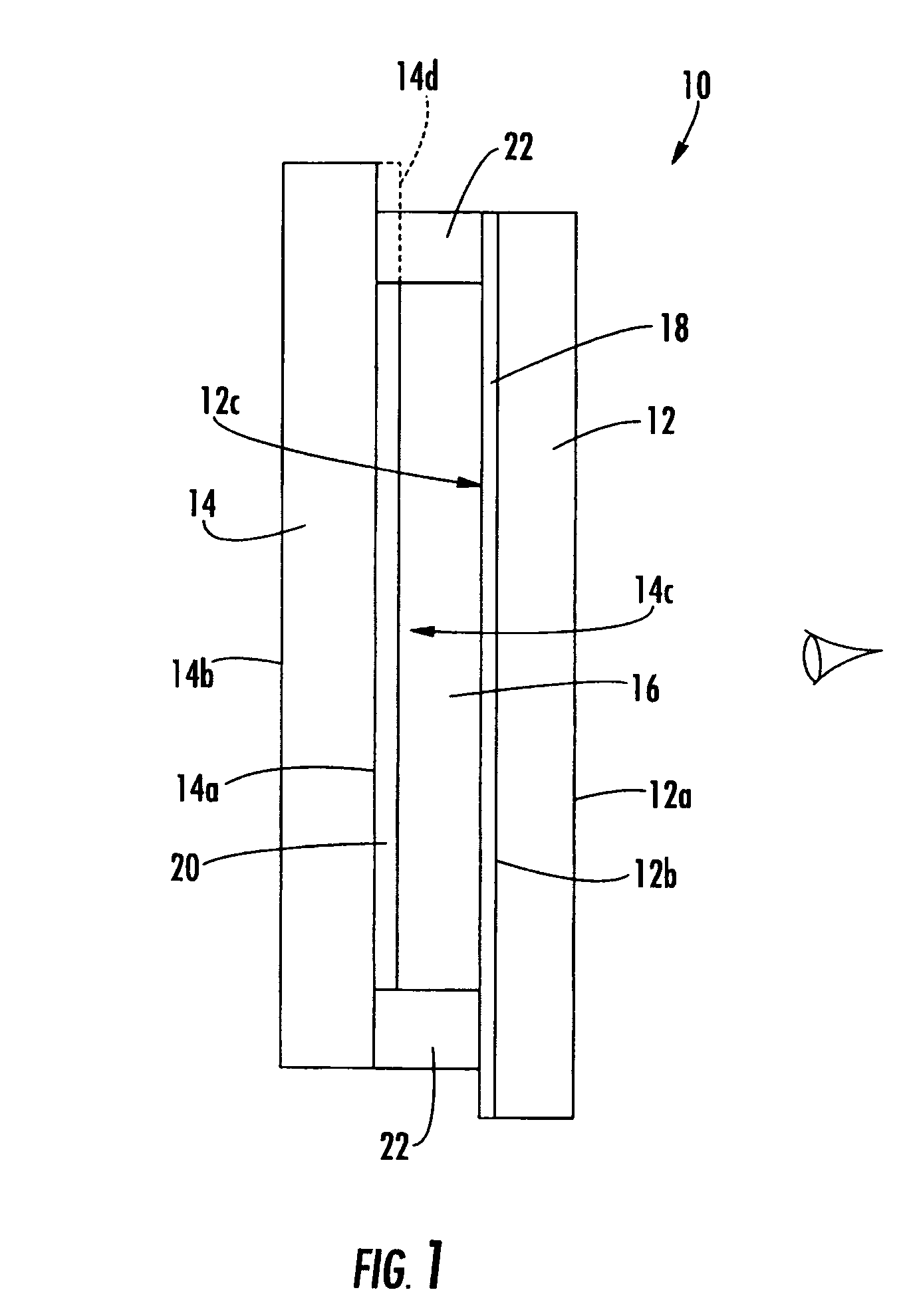
[0080] Referring now to the drawings and the illustrative embodiments depicted therein, a mirror reflective element assembly or cell 10 for an interior or exterior rearview mirror assembly of a vehicle includes a first or front substrate or glass element 12 and a second or rear substrate or glass element 14 (FIG. 1). The rear reflective element substrate 14 is spaced from front reflective element substrate 12, and the cell includes an electrolyte or monomer composition or electrochromic medium 16 and conductive or semi-conductive layers 18, 20 (described below) sandwiched therebetween. An epoxy seal material 22 or the like, is applied between the substrates to define the cavity for the electrochromic medium and to adhere the substrates together. The substrates may be adhered together while in a sheet form with other substrates or mirror shapes, as discussed below.

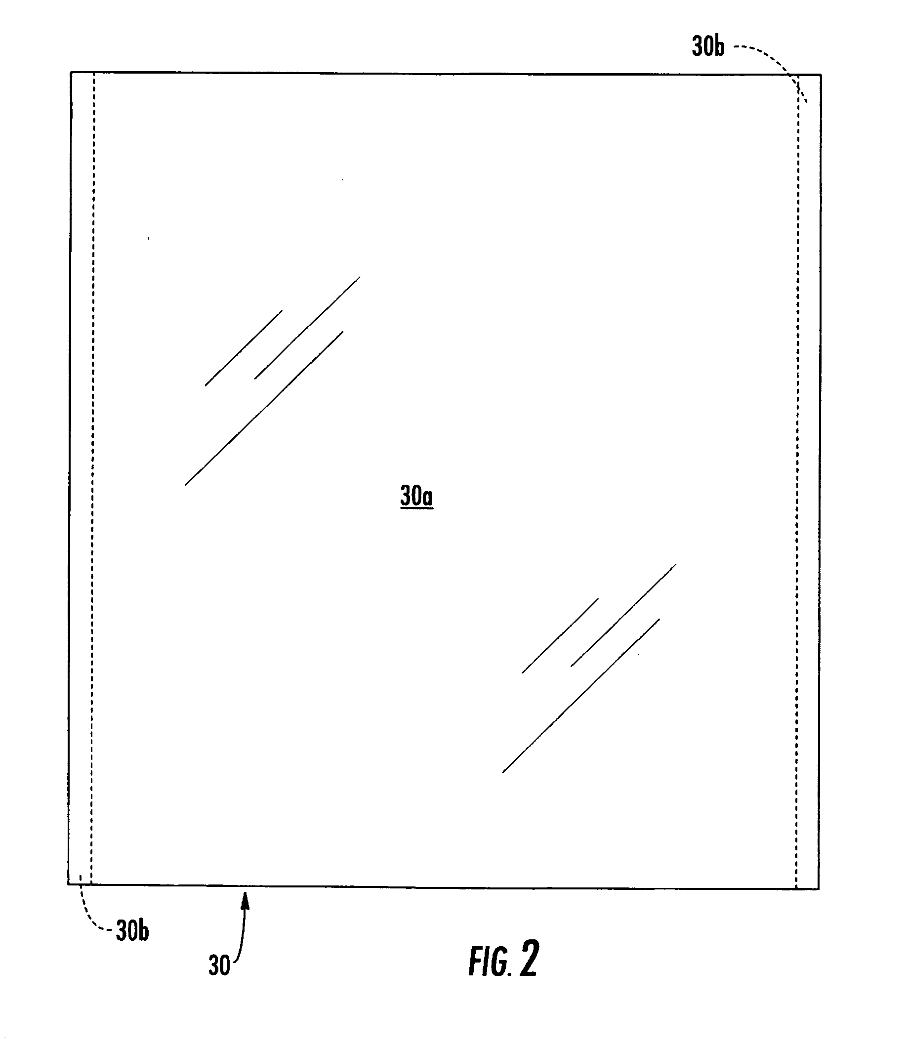
[0081] The present invention provides a process that adheres the mirror shapes together with the epoxy seal before the f...


PUM


Abstract

A reflective element assembly for a variable reflectance vehicular mirror includes a front substrate having a transparent conductive coating disposed on a second surface, and a rear substrate having a third surface conductive coating disposed on its third surface and preferably, a fourth surface conductive coating disposed on its fourth surface. At least a portion of the third surface conductive coating may wrap around an edge portion of the rear substrate and at least a portion of the fourth surface conductive coating may wrap around at least a second portion of the perimeter edge so as to establish electrical continuity between the fourth surface conductive coating on the fourth surface and the third surface conductive coating on the third surface. The rear substrate may have a smaller dimension than the front substrate so as to provide an overhang region, preferably at the wraparound region.

Description

CROSS REFERENCE TO RELATED APPLICATIONS [0001] The present application claims benefit of U.S. provisional applications, Ser. No. 60 / 531,838, filed Dec. 23, 2003 (Attorney Docket DON01 P-1132); Ser. No. 60 / 553,842, filed Mar. 17, 2004 (Attorney Docket DON01 P-1143); Ser. No. 60 / 563,342, filed Apr. 19, 2004 (Attorney Docket DON01 P-1153); and Ser. No. 60 / 629,926, filed Nov. 22, 2004 (Attorney Docket DON01 P-1190), and is a continuation-in-part of PCT Application No. PCT / US03 / 35381, filed Nov. 5, 2003 by Donnelly Corp. et al. for ELECTRO-OPTIC REFLECTIVE ELEMENT ASSEMBLY (Attorney Docket DON01 FP-1116(PCT)), which claims benefit of U.S. provisional applications, Ser. No. 60 / 490,111, filed Jul. 25, 2003 by McCabe et al. for FLUSH ELECTROCHROMIC CELL (Attorney Docket DON01 P-1102); and Ser. No. 60 / 423,903, filed Nov. 5, 2002 by McCabe for ONE SIDED FLUSH ELECTROCHROMIC CELL (Attorney Docket DON01 P-1032), and is a continuation-in-part of PCT Application No. PCT / US03 / 29776, filed Sep. 19,...

Claims


Application Information

Patent Timeline
IPC IPC(8): G02B5/08
CPCB60R1/088G02B5/08G02F1/1533Y10T428/24942G02F1/157B60R1/082G02F1/161B60R1/1207B60R2001/1215G02B5/085
Inventor MCCABE, IAN A.HABIBI, HAMIDLYNAM, NAILL R.BAREMAN, DONALD L.
Owner DONNELLY CORP
Why Eureka
Try Eureka