

Additive layering method using improved build description
- Summary
- Abstract
- Description
- Claims
- Application Information
AI Technical Summary
Benefits of technology
Problems solved by technology
Method used
Image

Examples
first embodiment
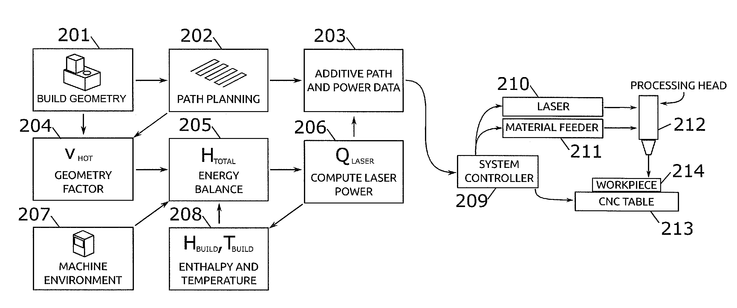
[0142]The last step of the inventive method includes calculating optimum beam source power Qsource for the point P(s) according to the following equation
Qsource=min(Qmax, Htotal / αΔt)
[0143]wherein Qmax represents maximum laser power, α represents a beam absorption coefficient and Δt represents a calculation interval.
[0144]The first embodiment inventive method can be refined further by enhancing the calculation of the idealized geometry by calculating a geometry index hot zone volume (Vhot) for the point P(s) on the additive path according to the formula
Vhot=G∩Z(rhot, P(s), t′(s))
[0145]wherein G represents deposition geometry, Z represents a hemisphere of a certain radius (r) and having a circular surface centered at a point P(s) on the additive path with a normal direction ({hacek over (n)}), rhot represents the radius of the hot zone and t′(s) represents tool axis direction at a distance s along the additive path; and
[0146]calculating a geometry index hot zone area (Ahot) for the po...
second embodiment
[0150]The second embodiment method further comprises calculating an energy loss of the part at point P(s) during the additive process, the calculation of energy loss being based upon the calculation of temperature and including a calculation of energy conducted from the melt pool to the hot zone; calculating an enthalpy of the part at point P(s) in time during the additive process; calculating total energy needed at the point P(s) based upon the calculated energy loss and enthalpy of the part at point P(s) on the additive path; and calculating an optimum beam source power based upon the calculation of total energy needed.
[0151]Using the calculations above, the laser energy delivered during an additive path deposition process can be controlled for each point along the path by regulating power to the laser at each point in accordance with the required power predicted by the above calculation methods. As such, in another embodiment of the invention the method can be programmed into a c...
PUM
 Abstract
Description
Claims
Application Information