Three-dimensional periodic structure, functional element including the same, and light-emitting device

a three-dimensional periodic structure and functional element technology, applied in the direction of optical waveguide light guide, instruments, nanotechnology, etc., can solve the problems of difficult realization of optical elements, e.g., waveguides and wavelength selection filters, which are operated in wide wavelength bands, and difficult to produce the inverse opal structur

Inactive Publication Date: 2005-09-08
CANON KK
View PDF5 Cites 14 Cited by
  • Summary
  • Abstract
  • Description
  • Claims
  • Application Information

AI Technical Summary

Benefits of technology

[0012] According to the present invention, a three-dimensional periodic structure exhibiting a complete photonic band gap in a wide wavelength band compared with that in the known three-dimensional periodic structure and being readily produced is provided. A functional element whi

Problems solved by technology

In general, three-dimensional periodic structures exhibiting photonic band gaps have structures that are small and are not readily producible.
Consequently, there is a problem in that realization of optical elements, e.g., waveguides

Method used


Image

  • Three-dimensional periodic structure, functional element including the same, and light-emitting device
  • Three-dimensional periodic structure, functional element including the same, and light-emitting device
  • Three-dimensional periodic structure, functional element including the same, and light-emitting device

Examples


first embodiment

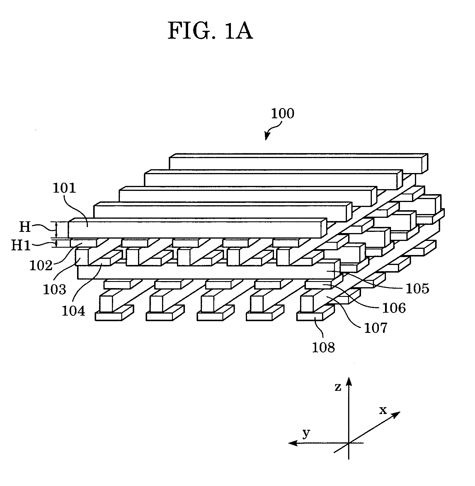
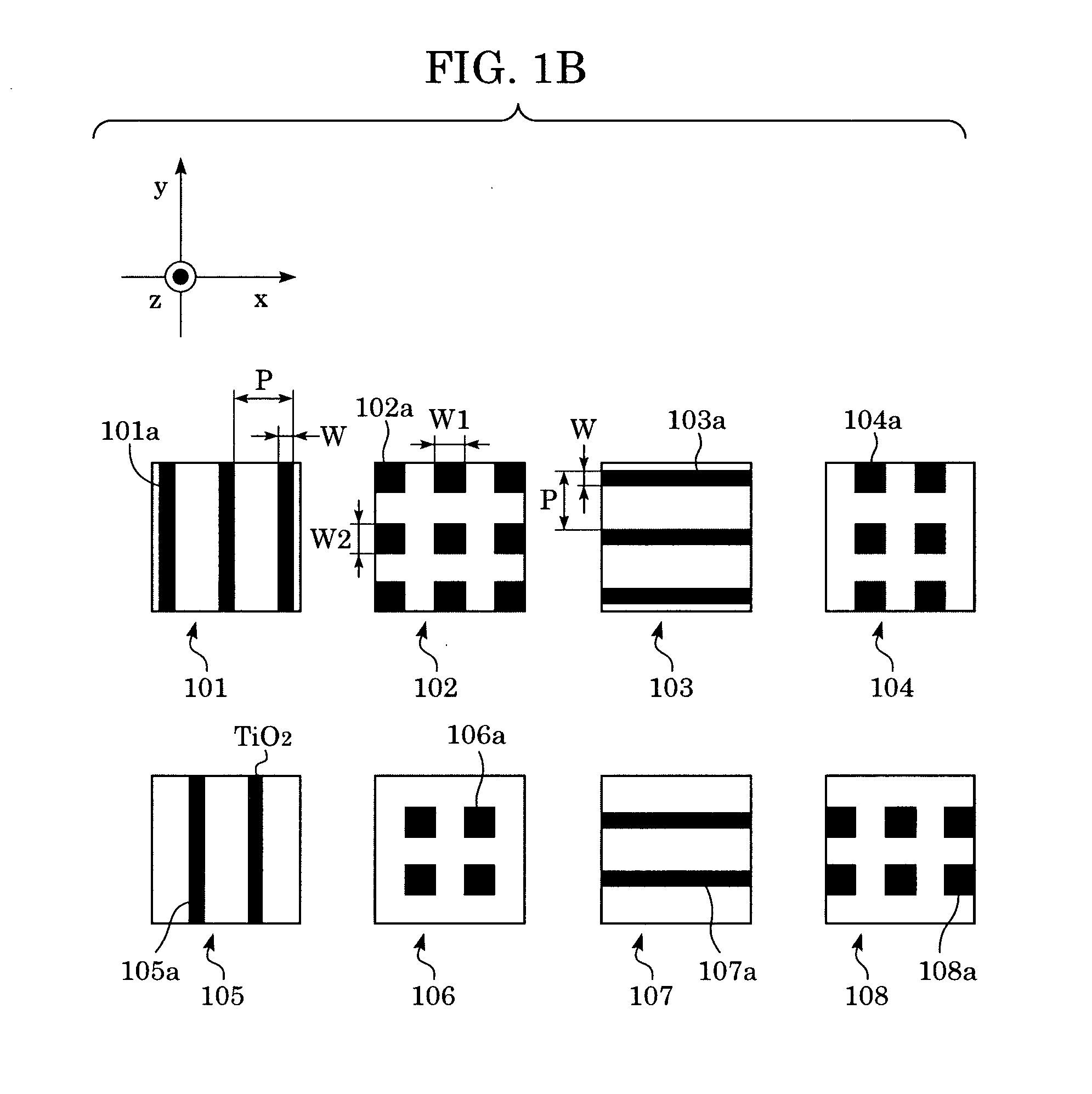
[0038]FIG. 1A is a perspective view of a key portion of a three-dimensional periodic structure in accordance with a first embodiment of the present invention. The three-dimensional periodic structure 100 includes eight layers 101 to 108 in x-y planes as a basic period. FIG. 1B is a perspective view showing a part of an x-y section of each of the layers 101 to 108. In the first layer 101 and the fifth layer 105, a plurality of square columns 101a and 105a made of a first medium (high refractive index) extending in the y axis direction are spaced at regular intervals (Pitches) P in the x direction, and the square columns 101a and 105a are arranged at positions shifted from each other by P / 2 in the x axis direction. In the third layer 103 and the seventh layer 107, a plurality of square columns 103a and 107a made of the first medium extending in the x axis direction are spaced at regular intervals P in the y direction, and the square columns 103a and 107a are arranged at positions shif...

second embodiment

[0060]FIG. 8A is a perspective view of a key portion of the second embodiment of the three-dimensional periodic structure of the present invention. The three-dimensional periodic structure 200 includes twelve layers composed of layers 201 to 212 in x-y planes as a basic period. FIG. 8B shows a part of an x-y section of each layer. In a first layer 201 and a seventh layer 207, a plurality of square columns 201a and 207a, respectively, made of a first medium extending in the y axis direction are spaced apart by a regular interval P in the x direction, and the square columns 201a and 207a are arranged at positions shifted from each other by P / 2 in the x axis direction. In a fourth layer 204 and a tenth layer 210, a plurality of square columns 204a and 210a, respectively, made of the first medium extending in the x axis direction are spaced apart by a regular interval P in the y direction, and the square columns 204a and 210a are arranged at positions shifted from each other by P / 2 in t...

third embodiment

[0069]FIG. 14A is a perspective view of a key portion of the third embodiment of the three-dimensional periodic structure of the present invention. The three-dimensional periodic structure 300 includes sixteen layers composed of layers 301 to 316 in x-y planes as a basic period. FIG. 14B shows a part of an x-y section of each layer. In a first layer 301 and a ninth layer 309, a plurality of square columns 301a and 309a, respectively, made of a first medium extending in the y axis direction are spaced at regular intervals P in the x direction, and the square columns 301a and 309a are arranged at positions shifted from each other by P / 2 in the x axis direction.

[0070] In a fifth layer 305 and a thirteenth layer 313, a plurality of square columns 305a and 313a, respectively, made of the first medium extending in the x axis direction are spaced at regular intervals P in the y direction, and the square columns 305a and 313a are arranged at positions shifted from each other by P / 2 in the ...


PUM


Abstract

A three-dimensional periodic structure exhibiting a complete photonic band gap in a wide wavelength range and being readily produced, as well as a functional element including the same, is provided. In the three-dimensional periodic structure exhibiting a photonic band gap according to the present invention, layers composed of a plurality of square columns spaced apart by a predetermined interval are stacked sequentially with additional layers therebetween, rectangular parallelepipeds contained in the additional layers are disposed at the positions corresponding to the intersections of the square columns, and 1.21≦W1/W≦2.39 and W/W1<W2/W are satisfied, where W1 and W2 represent lengths of sides of the rectangular parallelepiped and W represents the width of the square column, each in a plane parallel to the layer containing the square columns.

Description

BACKGROUND OF THE INVENTION [0001] 1. Field of the Invention [0002] The present invention relates to a three-dimensional periodic structure exhibiting a photonic band gap, a functional element including the same, and a light-emitting device. [0003] 2. Description of the Related Art [0004] The concept that the transmission-reflection characteristics and the like of an electromagnetic waves are controlled by a structure that is smaller than or equal to a wavelength of light has been previously proposed by Yablonovitch (Physical Review Letters, Vol. 58, pp. 2059, 1987). According to this document, the transmission-reflection characteristics and the like of electromagnetic waves can be controlled by periodically arranging structures smaller than or equal to the wavelength of light, and the transmission-reflection characteristics of light can be controlled by reducing the wavelength of the electromagnetic waves to an order of the wavelength of the light. Such a structure is known as a ph...

Claims


Application Information

Patent Timeline
IPC IPC(8): G02B6/12G02B6/122G02F1/365H01S5/12
CPCB82Y20/00G02B6/1225G02B6/12002
Inventor IKEMOTO, KIYOKATSUTAKAGI, AKINARIHOSHI, HIKARU
Owner CANON KK
Why Eureka
Try Eureka