High performance composite tubular structures

a tubular structure, composite technology, applied in the direction of golf clubs, sport apparatus, fishing, etc., can solve the problems of reducing the diameter and reducing the performance of the tubular structure. , to achieve the effect of enhancing performance, reducing buckling, and being lighter and/or more resistant to buckling

Inactive Publication Date: 2005-09-08
VYATEK SPORTS
View PDF42 Cites 17 Cited by
  • Summary
  • Abstract
  • Description
  • Claims
  • Application Information

AI Technical Summary

Benefits of technology

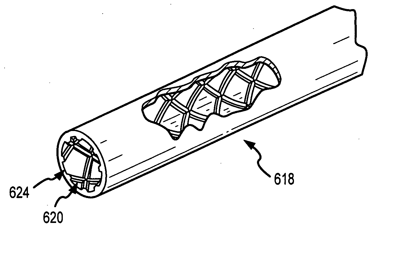
[0012] The present invention satisfies the needs described above by providing high performance, composite, tubular structures that are lighter and/or more resistant to buckling-related stress than conventional tubes. In general, the present invention incorporates features into the design of tubular structures to enhance performance.
[0013] For example, in accordance with one preferred embodiment of the present invention, tubular structures are enhanced by incorporating small, stabilizing, raised ribs on the ID or OD of the tubes. These ribs enable designers to optimize the tubes' inertial properties (area mass moments of inertia) to achieve lighter weight, greater stiffness, increased strength or some combination of all three. The ribs may be configured in a variety of shap

Problems solved by technology

The standard flag wrapping and filament wound processes for manufacturing high performance tubes have several drawbacks due to the fact that, during consolidation/curing, the diameter of the tube is reduced.
This reduction in diameter typically makes the final OD surface rough and irregular, thus requiring secondary finishing by centerless grinding and sanding.
However, the grinding/sanding process also typically cuts and abrades the outermost fibers of a tubular structure.
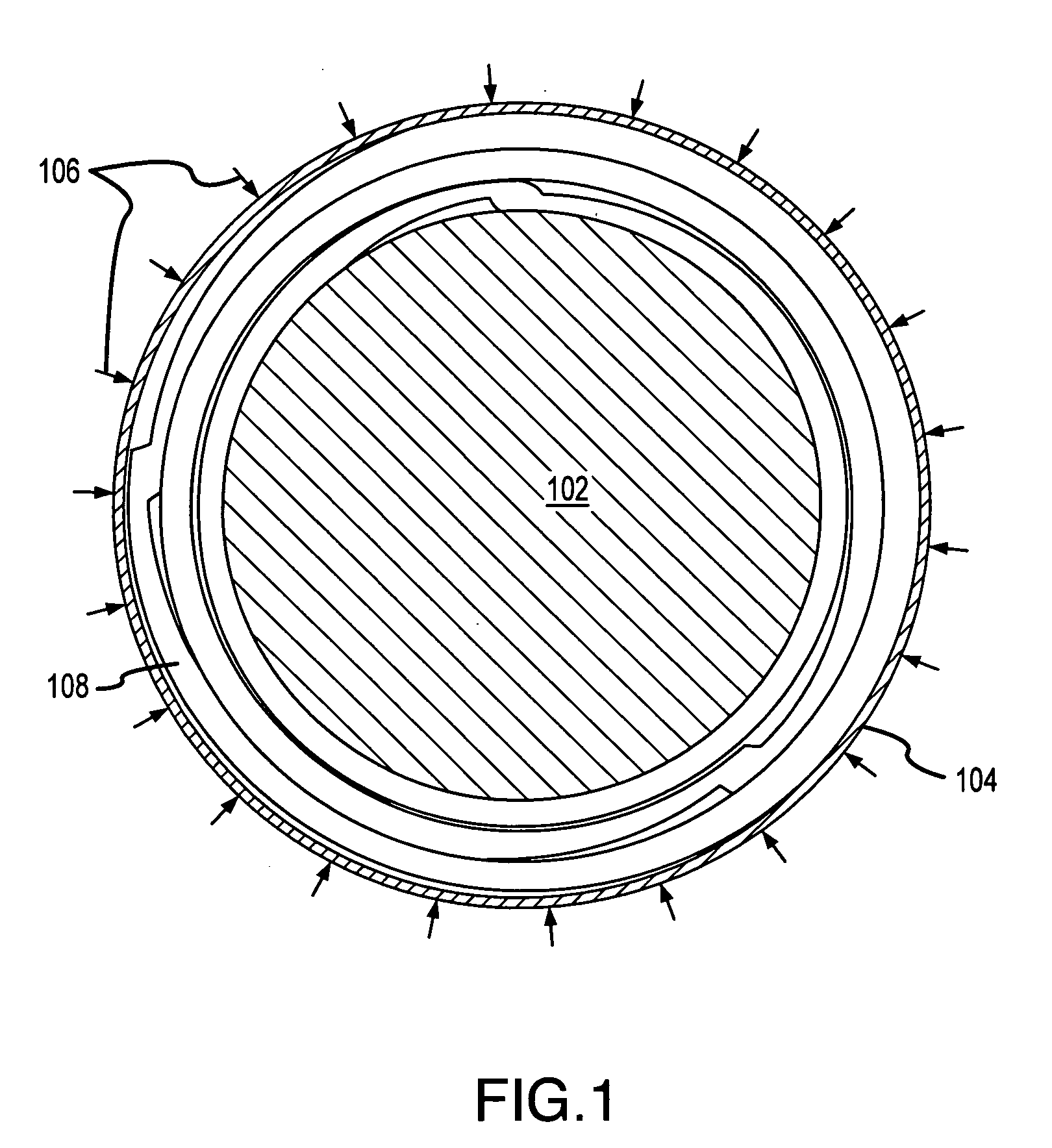
Because these outermost fibers are the most highly stressed due to their location (i.e., a max=MC/I, where “C” is the distance to the outside layer), the grinding/sanding process usually reduces the structural integrity of a tubular structure.
Though the net molding technique may be an improvement over the shrink wrapping techniques, prior art methods for producing high performance, composite, tubular struct

Method used


Image

  • High performance composite tubular structures
  • High performance composite tubular structures
  • High performance composite tubular structures

Examples


Embodiment Construction

[0023] The following descriptions are of exemplary embodiments of the invention only, and are not intended to limit the scope, applicability or configuration of the invention in any way. Rather, the following description is intended to provide convenient illustrations for implementing various embodiments of the invention. As will become apparent, various changes may be made in the function and arrangement of the elements described in these embodiments without departing from the sprit and scope of the invention. For example, as described herein, integral ribs in accordance with the present invention are described as having a helical configuration, though, as mentioned above, various alternative configurations of ribs may likewise be used and still fall within the ambit of the appended claims.

[0024] That being said, with reference to FIGS. 4a-4c and 5a-5c and in accordance with one exemplary embodiment of the present invention, an expandable, elastomeric tube 408, with an outer surfa...


PUM

PropertyMeasurementUnit
Angleaaaaaaaaaa
Angleaaaaaaaaaa
Angleaaaaaaaaaa

Abstract

This invention relates generally to the design and manufacture of high performance, composite, tubular structures. More specifically, the invention relates to a high performance, composite, tubular structure that utilizes an integral pattern of ribs on the internal diameter (“ID”) or outer diameter (“OD”) surface of the tube. The present invention provides high performance, composite, tubular structures that are both lighter and stiffer than conventional tubes. In general, the present invention incorporates unconventional features into the design of tubular structures, to greatly enhance performance. For example, in accordance with one preferred embodiment of the present invention, tubular structures are enhanced by incorporating small, stabilizing, raised ribs on the ID of the tubes.

Description

CROSS-REFERENCES TO RELATED APPLICATIONS [0001] This application claims priority to to U.S. patent application Ser. No. 09 / 881,591 entitled “High Performance Composite Tubular Structures.”BACKGROUND OF THE INVENTION [0002] 1. Technical Field of the Invention [0003] This invention relates generally to the design and manufacture of high performance, composite, tubular structures. More specifically, the invention relates to high performance, composite, tubular structures that utilize an integral pattern of reinforcing ribs on the inner diameter (“ID”) or outer diameter (“OD”) surface of the tube. [0004] 2. Background of the Prior Art [0005] Thin-walled, high performance, tubular structures have a wide variety of practical uses, such as for graphite composite golf shafts, arrows, bats, ski poles, hockey sticks, bicycle parts and many other applications. Current state of the art, high performance, tubular structures are constructed by various methods and from various materials. Designers...

Claims


Application Information

Patent Timeline
IPC IPC(8): A63B53/10A01K87/00A63B59/00B29C53/38B29C70/06B29C70/34B29C70/44B32B1/08F16L9/147
CPCA63B53/10A63B59/0014A63B59/0077A63B2209/02B29C53/385Y10T428/139B29C70/446F16L9/147Y10S138/11Y10T428/1393B29C70/342A63B60/48A63B60/06A63B60/08A63B60/00A63B60/10
Inventor LINDSAY, HOWARD A.
Owner VYATEK SPORTS
Why Eureka
Try Eureka