
Administration apparatus for medical use

a technology for administering equipment and medical devices, which is applied in the direction of packaging foodstuffs, packaged goods types, pharmaceutical containers, etc., can solve the problems of inconvenient and troublesome operation, increase in and disadvantage in handling, so as to facilitate the replacement of cartridges and minimize the size of the injector

Inactive Publication Date: 2005-09-08
PANASONIC CORP
View PDF7 Cites 145 Cited by
  • Summary
  • Abstract
  • Description
  • Claims
  • Application Information

AI Technical Summary

Benefits of technology

[0015] The present invention is made to solve the above-described problems and has for its object to provide an administration apparatus for medical use which enables a patient to easily replace cartridges, and minimizes the size of an injector itself.
[0016] It is another object of the present invention to provide an administration apparatus for medical use which eases physical and mental pains on a patient by detecting abnormal operation during injection and informing it to a patient, thereby enabling the patient to carry out administration of a drug with high stability.

Problems solved by technology

In the conventional injector, however, the patient must detach the cartridge holder into which the drug cartridge is inserted from the body of the injector, detach the drug cartridge from the cartridge holder, attach a new drug cartridge to the holder, and mount the cartridge holder onto the injector body, resulting in inconvenient and troublesome operation.
Therefore, the length of the injector itself becomes at least two times as long as the drug cartridge, leading to an increase in the size of the injector.
However, since the piston has a curvature, the thickness of the injector is increased, leading to a disadvantage in handleability.
The act of drug administration itself gives mental stress onto the patient, and furthermore, abnormal operation of the motor-operated injector greatly affects the human body, which may endanger the life of the patient.
The conventional administration apparatus for medical use is constructed as described above, and the operation of cartridge replacement is troublesome.
Further, the size of the apparatus is too large to handle.
Furthermore, as for the motor-operated apparatus, the patient might be anxious during drug administration about air releasing before injection, the operation state of the mechanism, or the like.

Method used


Image

  • Administration apparatus for medical use
  • Administration apparatus for medical use
  • Administration apparatus for medical use

Examples


embodiment 1

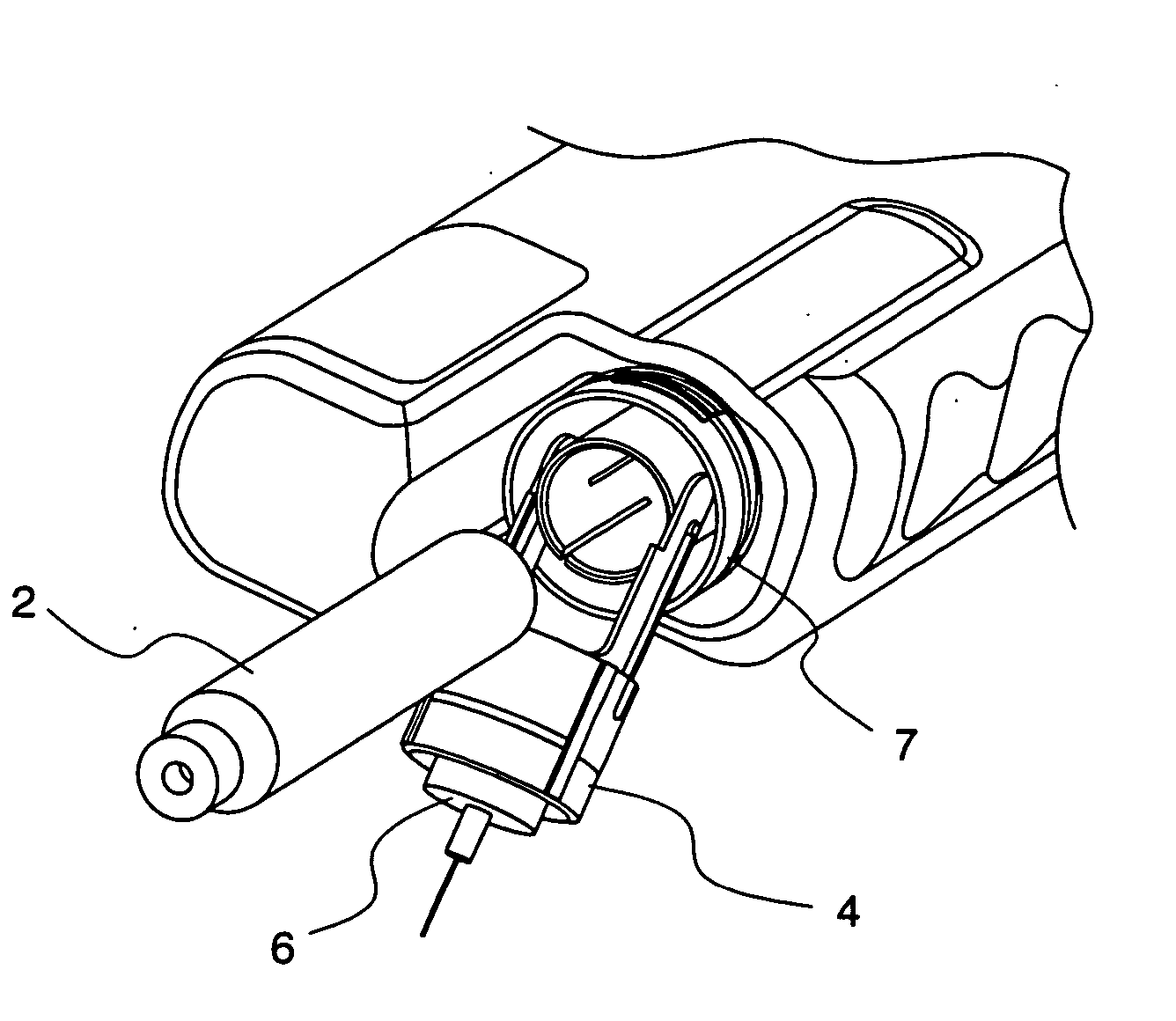
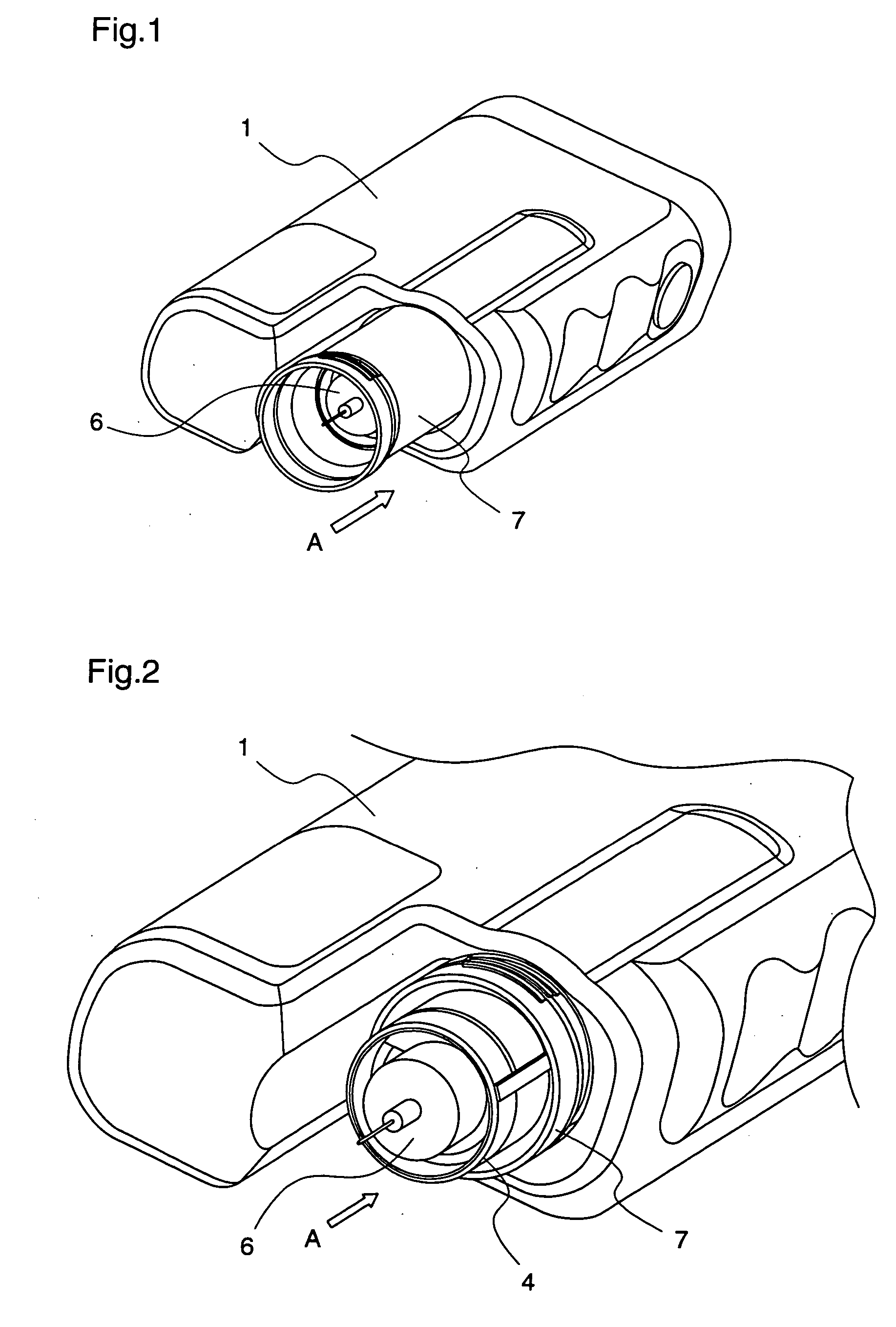
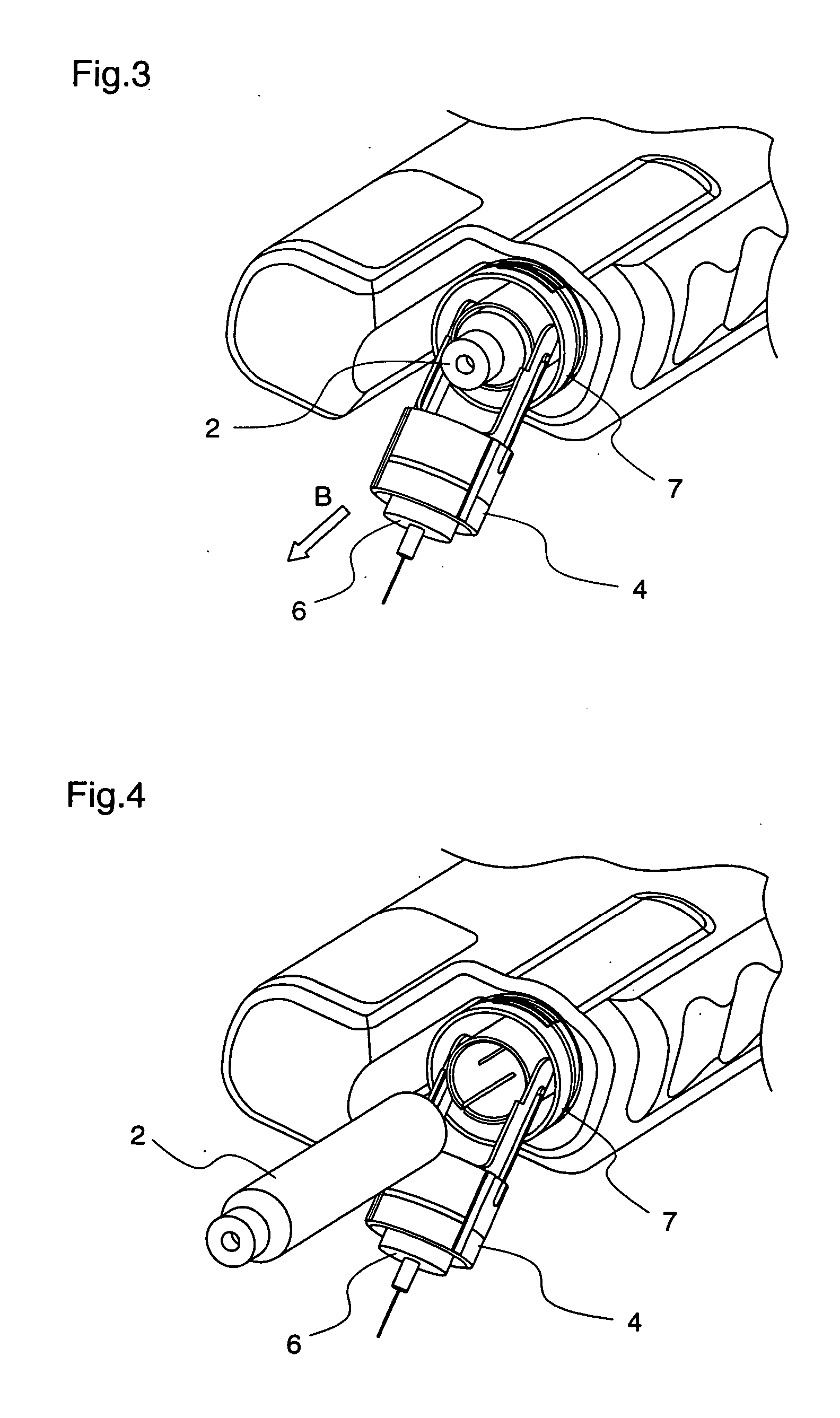
[0071]FIG. 1 is a diagram illustrating the whole construction of an administration apparatus for medical use according to a first embodiment of the present invention.

[0072] In FIG. 1, reference numeral 1 denotes an administration apparatus having, at an end thereof, a target-region contact cover 7 to be applied to a target region of patient's body to be subjected to injection when the patient performs administration by himself, and a needle assembly 6 is housed in the cover 7.

[0073] Further, a drug cartridge containing a drug, an end of which is closed with a plunger (not shown), is inserted in the administration apparatus. When the needle assembly 6 pierces the target region, a piston rod (not shown) that presses the plunger moves, whereby the drug emitted from an end of the drug cartridge is injected into the patient's body.

[0074] When the patient replaces the drug cartridge, the target-region contact cover 7 is slid in the direction of arrow A as shown in FIG. 2, whereby the n...

embodiment 2

[0089] Next, an administration apparatus for medical use according to a second embodiment of the present invention will be described. FIG. 11 is a diagram illustrating a piston rod assembly of a motor-operated administration apparatus for medical use according to a second embodiment of the present invention. As shown in FIG. 11, a bush shaft 11 having a length approximately equal to the whole length of the rod assembly and having a male thread (not shown) on its periphery is pushed into a driving gear 10 for transferring a driving power from a motor or the like (not shown). Further, a hollow piston rod A12 having, on its inner periphery, a female thread (not shown) that is screwed with the male thread of the bush shaft 11 has a male thread (not shown) on its periphery. Furthermore, a piston rod B14 having, on its inner periphery, a female thread (not shown) that is screwed with the piston rod A12 is screwed with the piston rod A12. How the bush shaft 11, the piston rod A12, and the ...

embodiment 3

[0096] Next, an administration apparatus for medical use according to a third embodiment of the present invention will be described with reference to FIGS. 16 to 19.

[0097]FIG. 16 is a perspective view for explaining the internal structure of an administration apparatus for medical use according to the third embodiment, FIG. 17 is a perspective view illustrating the external appearance of the administration apparatus, FIG. 18 is a block diagram for explaining connections in the administration apparatus as an electric circuit, and FIG. 19 is a flowchart for explaining the operation of the administration apparatus.

[0098] Initially, FIG. 16 will be described.

[0099]FIG. 16 is a diagram illustrating the construction of a motor-operated administration apparatus for medical use which performs an operation of administrating a drug using an electric driving source.

[0100] In FIG. 16, a syringe (drug cartridge) 101 filled with a drug is set in a cartridge holder 103 that is attached to a bo...


PUM


Abstract

An expansion / compression mechanism of a piston rod assembly is composed of a bush shaft, a first cylindrical piston rod that is screwed with the bush shaft, a second cylindrical piston rod that is screwed with the first piston rod, and a piston rod holding member for housing the bush shaft and the piston rods. Therefore, the piston rods move linearly in multiple stages, whereby the size of the whole apparatus is reduced.

Description

FIELD OF THE INVENTION [0001] The present invention relates to an administration apparatus for medical use which is driven by an electric driving source to perform administration of a drug and, more particularly, to an administration apparatus that facilitates replacement of drug cartridges. BACKGROUND OF THE INVENTION [0002] A patient addicted to insulin must get plural times of injections of insulin per week or day. The required amount of insulin varies from patient to patient. The required amount of insulin for each patient varies from injection to injection, and it also varies from day to day. [0003] A patient who performs injection by himself attaches a drug cartridge containing a drug to an injector, and attaches a needle assembly to an elastic seal of the drug cartridge, and thereafter, sets the dose, and operates the injector to inject the drug into his body. The drug in the drug cartridge runs out when such administration is carried out a few times. The patient detaches the...

Claims


Application Information

Patent Timeline
IPC IPC(8): A61J1/06A61K9/22A61M5/178A61M5/24A61M5/315
CPCA61M5/20A61M5/3146A61M2005/206A61M2005/2073A61M2005/208A61M2005/2411A61M2005/31588A61M2005/3126A61M2005/31518A61M2205/50A61M2205/52A61M2205/581A61M2205/583A61M2005/2496A61M5/31535A61M5/31541A61M5/31546A61M5/14566A61M5/172A61M2205/12
Inventor SUGIMOTO, HIROHUMIMATSUDA, KOUICHIIIO, TOSHIAKIKIKUCHI, SEIJITAKEUCHI, YOSHIKI
Owner PANASONIC CORP
Learn More