Multilayer system and clock control method

Inactive Publication Date: 2005-09-08
RENESAS ELECTRONICS CORP
View PDF7 Cites 4 Cited by
  • Summary
  • Abstract
  • Description
  • Claims
  • Application Information

AI Technical Summary

Benefits of technology

[0013] According to one aspect of the present invention, there is provided a multilayer system that includes a plurality of masters; a plurality of slaves; a multilayer switch disposed between the masters and the slaves and simultaneously processing commands from the plurality of masters; and a clock generator supplying a clock signal to the masters, the slaves, and the multilayer switch, wherein the plurality of masters comprise a first master to which a clock signal is constantly supplied from the clock generator, and a second master to which a clock signal is supplied as needed, when activating the second master by the first master, the first master outputs an activation signal for activating the second master to the second master through a slave corresponding to the second master, the second master is activated in response to the activation signal and outputs to the clock generator a clock request signal requesting supply of a clock signal to the second master, and the clock generator supplies a clock signal to the second master in response to the clock request signal. Since the second master is activated by the activation signal and outputs to the clock generator a clock request signal that requests supply of a clock to the second master so that the clock generator supplies a clock signal to the second master in response to the clock request signal in this invention, it is possible to reduce a time to supply the clock signal and achieve power saving of the circuit.
[0014] According to one aspect of the present invention, there is provided a clock supply method in a multilayer system including a plurality of masters; a plurality of slaves; a multilayer switch disposed between the masters and the slaves and simultaneously processing commands from the plurality of masters; and a clock generator supplying a clock signal, the plurality of masters having a first master to which a clock signal is constantly supplied from the clock generator and a second master to which a clock signal is supplied as needed, the method including, when activating the second master by the first master, outputting from the first master an activation signal for activating the second master to the second master through a slave corresponding to the second master; activating the second master in response to the activation signal and outputting from the second master to the clock generator a clock request signal requesting supply of a clock signal to the second master; and supplying from the clock generator a clock signal to the second master in response to the clock request signal. Since this invention includes activating the second master by the activation signal so that the second master outputs to the clock generator a clock request signal that requests supply of a clock to the second master, and supplying from the clock generator a clock signal to the second master in response to the clock request signal in this invention, it is possible to reduce a time to supply the clock signal and achieve power saving of the circuit.
[0015] The present invention provides a multilayer system with low power consumption and a clock control method in the multilayer system.

Problems solved by technology

Each module receives a clock signal and operates, thereby consuming power.
However, these buses do not have a multilayer switch function that allows simultaneous processing of commands from a plurality of masters.

Method used


Image

  • Multilayer system and clock control method
  • Multilayer system and clock control method
  • Multilayer system and clock control method

Examples


Embodiment Construction

[0023] The invention will be now described herein with reference to illustrative embodiments. Those skilled in the art will recognize that many alternative embodiments can be accomplished using the teachings of the present invention and that the invention is not limited to the embodiments illustrated for explanatory purposed.

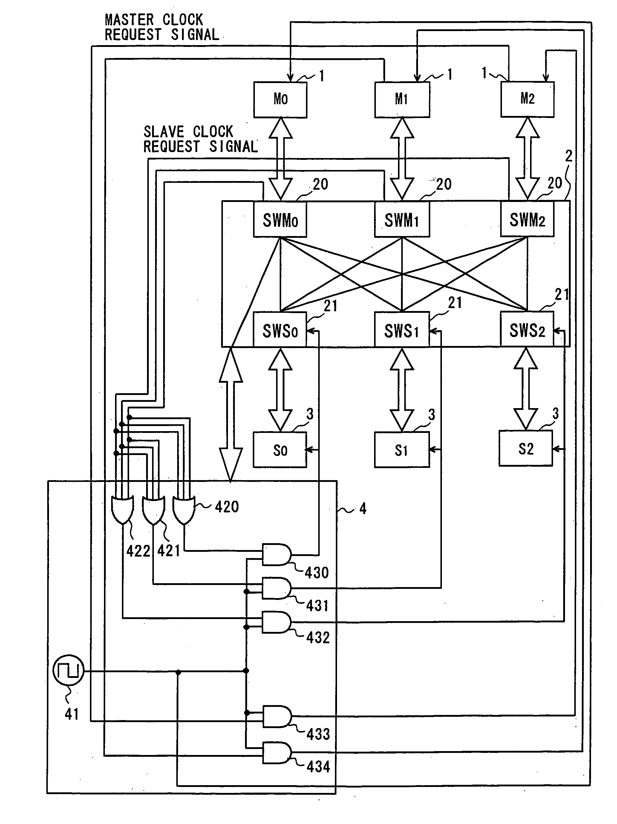
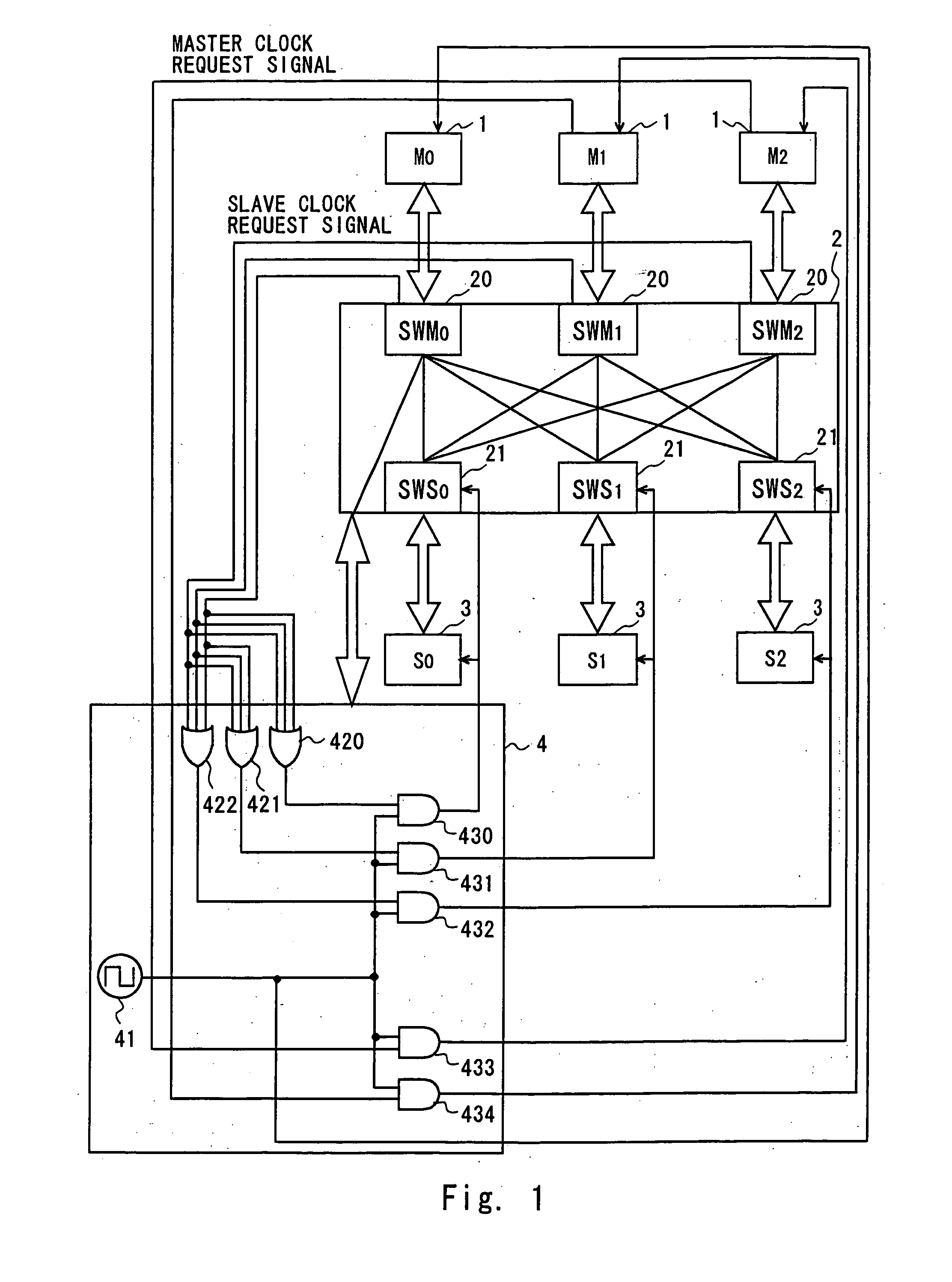
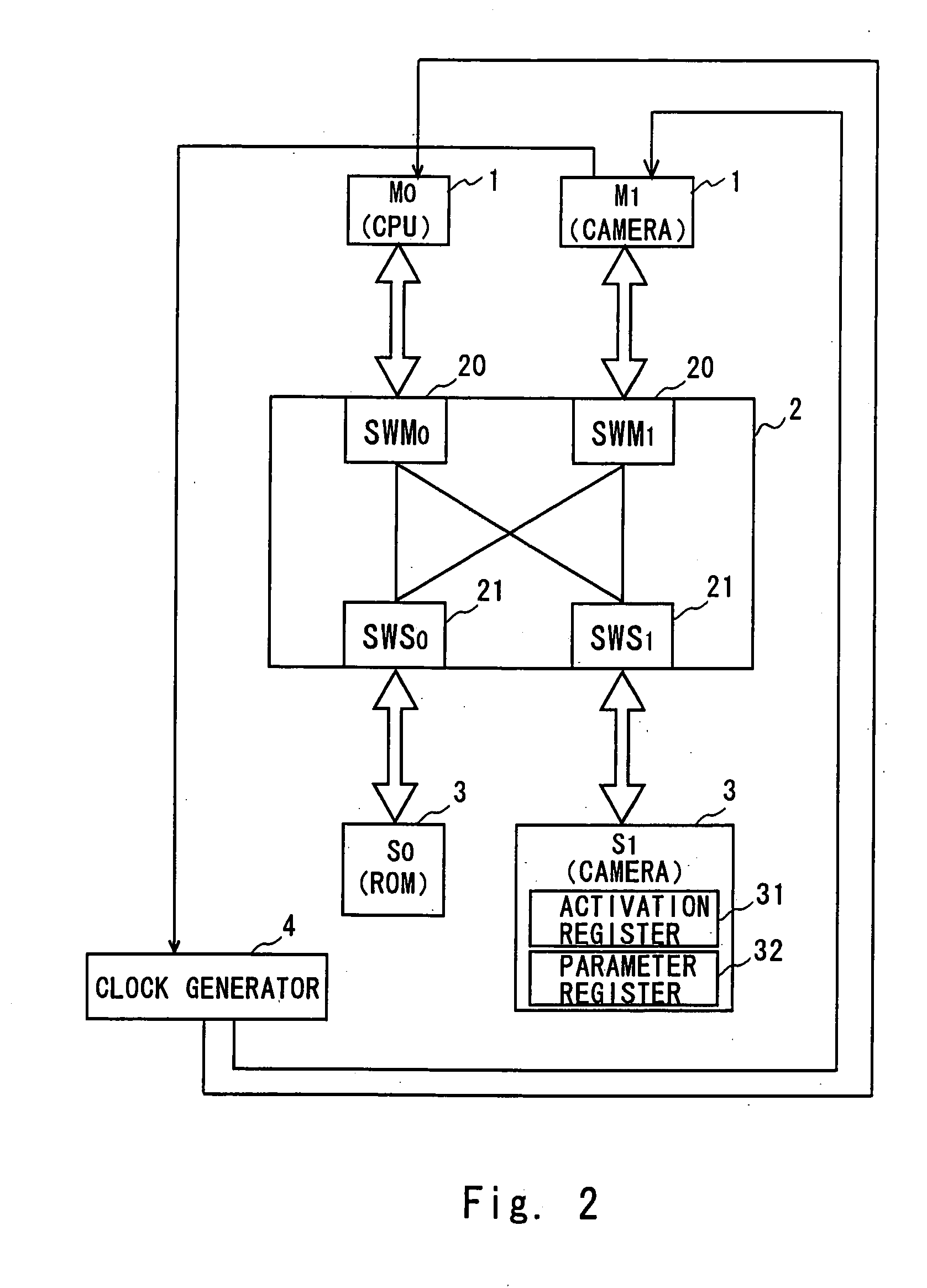
[0024]FIG. 1 shows a block diagram of a multilayer system of the present invention. The multilayer system includes a plurality of masters 1 (M0, M1, M2), a plurality of slaves 3 (S0, S1, S2), a multilayer switch 2 for the masters 1 and the slaves 3, and a clock generator 4 supplying a clock signal to each module.

[0025] The master 1 is a module that controls the system, such as Central Processor Unit (CPU), Digital Signal Processor (DSP), image rotating device, camera image processing circuit, Liquid Crystal Display (LCD) controller, and so on. In this example, the M0 is a CPU that always operates. The M1 and M2 are modules that operate as needed according to i...


PUM


Abstract

The multilayer system of this invention is characterized by the process when a first master such as a CPU to which a clock signal is constantly supplied from a clock generator activates a second master. First, the first master outputs an activation signal for activating the second master to the second master through a slave corresponding to the second master. The second master is activated by the activation signal and outputs to the clock generator a clock request signal for requesting supply of a clock signal to the second master. The clock generator supplies a clock signal to the second master in response to the clock request signal.

Description

BACKGROUND OF THE INVENTION [0001] 1. Field of the Invention [0002] The present invention relates to a multilayer system including a multilayer switch which allows simultaneous processing of commands from a plurality of masters and a clock control method in the multilayer system. [0003] 2. Description of Related Art [0004] Recent mobile phones have become multifunctional, having not only telephone functions but also internet connection functions, camera functions and so on. Further, in order to realize downsizing, weight saving, and reduction in power consumption, System on Chip (SoC) technology which incorporates multiple functions on one chip has been developed. [0005] Such mobile phones require high speed, simultaneous processing. Thus, a multilayer switch which allows simultaneous access to a plurality of slaves has been proposed. [0006] Use of the multilayer switch permits to carry out a process of writing image data from a camera into a given memory region and a process of rea...

Claims


Application Information

Patent Timeline
IPC IPC(8): G06F1/32G06F1/10G06F13/00H04Q7/32
CPCG06F1/3237Y02B60/1221G06F2213/0038Y02D10/00D06H7/06D06H7/223B26D7/20
Inventor HOSHI, SACHIKONARIAI, KYOICHI
Owner RENESAS ELECTRONICS CORP
Why Eureka
Try Eureka