Duel controller system for dynamically allocating control of disk units

a disk array and controller technology, applied in the direction of memory adressing/allocation/relocation, multi-programming arrangements, instruments, etc., can solve the problems of reducing cache capacity, inability to switch, and inability to apply conventional techniques to disk array apparatuses of the type, so as to avoid the concentration of access to the shared cache environment and improve cost performance and scalability. , the effect of improving the scalability

Inactive Publication Date: 2005-09-08
HITACHI LTD
View PDF7 Cites 13 Cited by
  • Summary
  • Abstract
  • Description
  • Claims
  • Application Information

AI Technical Summary

Benefits of technology

[0008] In a disk array system in the distributed cache environment wherein each controller has an independent and dedicated cache, each controller manages each volume by using the dedicated cache. Therefore, access concentration upon the shared cache environment can be avoided and cost performance and scalability can be improved.

Problems solved by technology

However, the conventional techniques cannot be applied to a disk array apparatus of the type that each controller has its own cache.
However, in the disk array system in the distributed cache environment wherein each controller has an independent and dedicated cache, even if a disk apparatus under the management of one controller is to be switched to another controller, this switching is impossible because the destination controller has input / output data of volumes to be switched.
Therefore, the cache capacity is lowered and the merit of distributed caches is lost.

Method used


Image

  • Duel controller system for dynamically allocating control of disk units
  • Duel controller system for dynamically allocating control of disk units
  • Duel controller system for dynamically allocating control of disk units

Examples


first embodiment

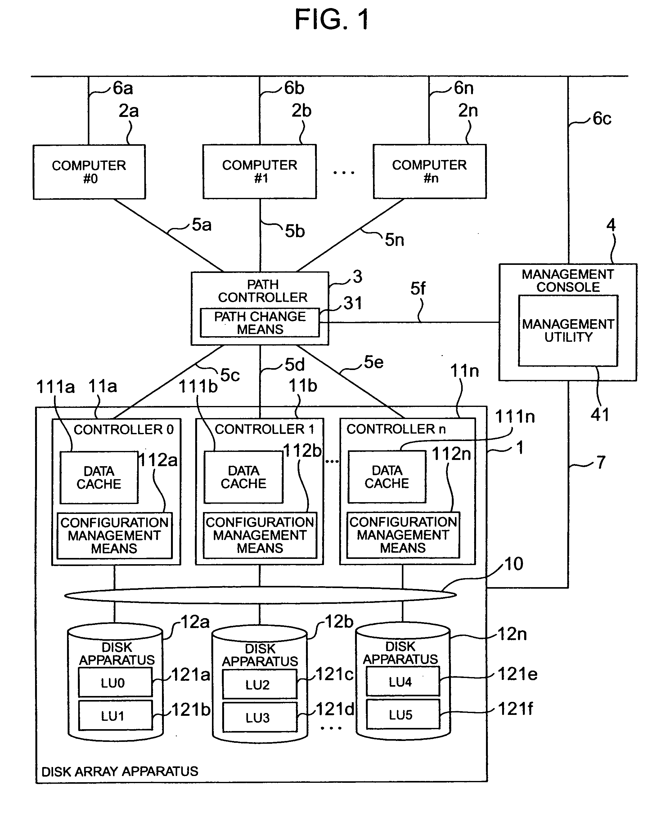
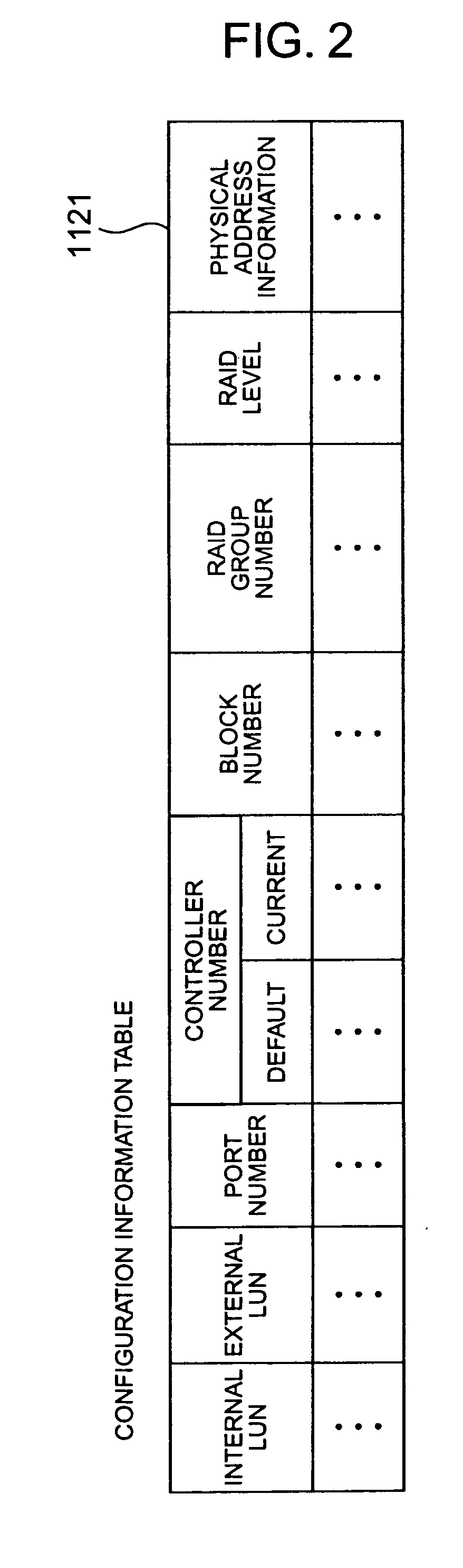
[0029]FIG. 1 is a block diagram showing the configuration of a disk array system according to the invention, and FIG. 2 is a diagram showing an example of the structure of a configuration information table possessed by configuration management means. In FIGS. 1 and 2, reference numeral 1 represents a disk array apparatus, reference symbol 2x(x=a, b, . . . , n) represents computers, reference numeral 3 represents a path controller, reference numeral 4 represents a management console, reference symbol 5x(x=a, b, . . . , n) represents channel paths, reference symbol 6x(x=a, b, . . . , n) represents local area networks (LAN), reference numeral 7 represents communication means, reference numeral 10 represents a device network, reference symbol 11x (x=a, b, . . . , n) represents controllers, reference symbol 12x(x=a, b, . . . , n) represents disk apparatuses each including general disks of, for example, 144 GB, reference numeral 31 represents path change means, reference numeral 41 repres...

second embodiment

[0058]FIG. 6 is a block diagram showing the configuration of a disk array system according to the invention. In FIG. 6, reference numeral 20 represents a tape read / write apparatus, and other reference numerals are the same as those shown in FIG. 1.

[0059] Different points of the second embodiment of the invention shown in FIG. 6 from the first embodiment shown in FIG. 1 reside in that the computer 2n is connected to the tape read / write apparatus 20 and each computer 2x is directly connected to a corresponding controller 11x. Similar to the first embodiment, it is obvious that the computer 2x and controller 11x may be interconnected via a path controller. The second embodiment can omit the path change means. It is not necessary that the computer 2x and controller 11x are in one-to-one correspondence, but a plurality of computers may be connected to one controller.

[0060] The second embodiment of the invention shown in FIG. 6 has a data mirroring function and the computer 2n is used as...


PUM


Abstract

A disk array system of the type that each controller has an independent and dedicated cache. The disk array system can change control of a desired volume between desired controllers without suspending the system. When volumes are taken over between controllers, a switch-source controller de-stages data of a subject volume on the data cache to a storage subject disk to maintain the disk content reflection (coherency). Even if each controller has an independent and dedicated cache, a desired volume can be taken over between desired controllers without suspending the system. Each controller has a configuration manager which stores the controller number of a switch-destination controller to allow automatic volume take-over and automatic control by the original controller.

Description

BACKGROUND OF THE INVENTION [0001] The present invention relates to a disk array system and a take-over method for logical units between controllers, and more particularly to a disk array system each of whose controllers has a dedicated cache and a take-over method for logical units between controllers. [0002] A conventional disk array system has a plurality of disks and controllers and a shared cache accessible by each controller. [0003]FIG. 10 is a block diagram showing the structure of a disk array system having a shared cache according to conventional techniques. Conventional techniques will be described with reference to FIG. 10. In FIG. 10, reference numeral 100 represents a large disk array apparatus, reference symbol 200x (x=a, . . . , n) represents controllers, reference numeral 300 represents an expensive shared cache, reference numeral 400 represents a shared memory, reference symbol 500x (x=a, . . . , n) represents disk apparatuses, and reference numeral 600 represents a...

Claims


Application Information

Patent Timeline
Patent Type & Authority Applications(United States)
IPC IPC(8): G06F3/06G06F11/20G06F12/00G06F12/08G06F12/16G06F13/00G06F13/12
CPCG06F3/0607G06F2212/284G06F3/0617G06F3/0629G06F3/0635G06F3/0647G06F3/065G06F3/067G06F3/0689G06F11/2033G06F11/2092G06F12/0866G06F2206/1012G06F2212/262G06F3/0613
Inventor MIZUNO, YOICHIMATSUNAMI, NAOTOMIMATSU, YASUYUKITAKAMOTO, KENICHI
Owner HITACHI LTD
Why Eureka
Try Eureka