
Lubricant cleansing apparatus for dry-type wire drawing
a technology of lubricant and cleaning apparatus, which is applied in the direction of cleaning equipment, manufacturing tools, lighting and heating apparatus, etc., can solve the problems of difficult to keep the pressure of lubricant in a predetermined state, easy to break the lubricant, and environmental contamination, so as to prevent environmental contamination
- Summary
- Abstract
- Description
- Claims
- Application Information
AI Technical Summary
Benefits of technology
Problems solved by technology
Method used
Image

Examples
Embodiment Construction
[0030] Preferred embodiments of the present invention will now be described in detail with reference to the accompanying drawings.
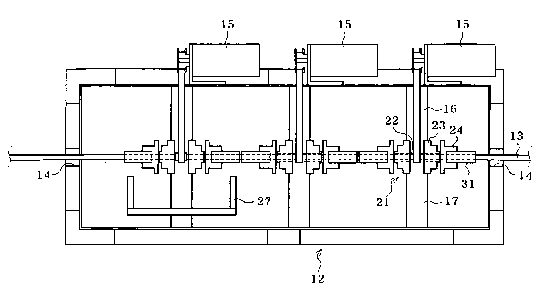
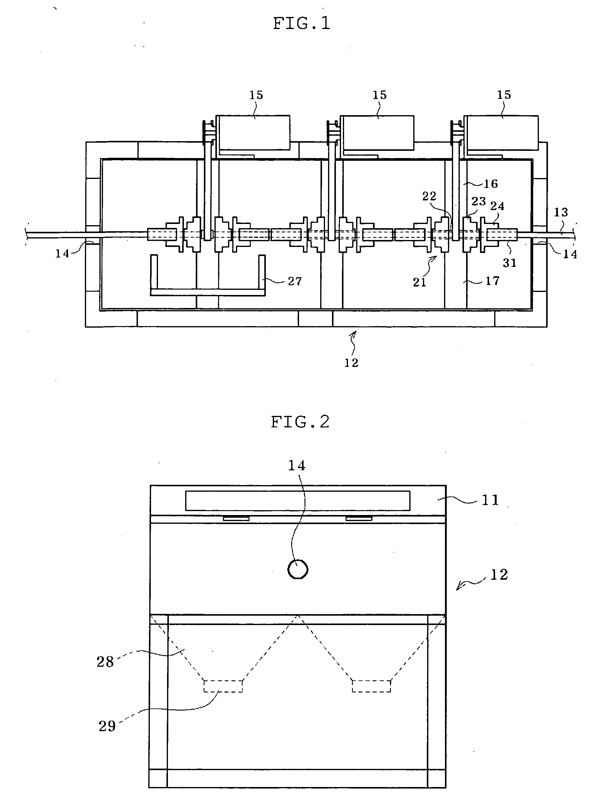
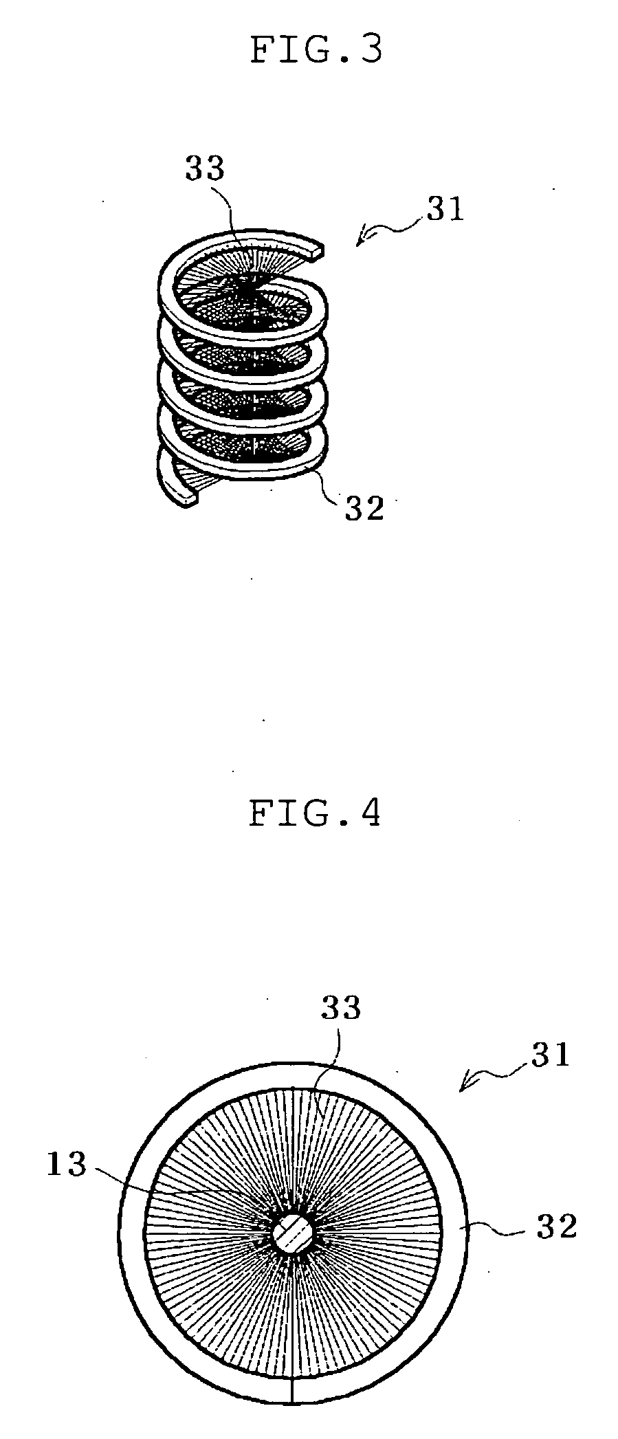
[0031]FIG. 1 is a view illustrating an apparatus for cleaning a lubricant for dry type wire drawing according to the present invention, and FIG. 2 is a sectional side elevation of the apparatus of FIG. 1. FIG. 3 is a view illustrating a cleaning member of the apparatus of FIG. 1, and FIG. 4 is a cross sectional view of the cleaning member of FIG. 1.
[0032] As shown in the drawings, the apparatus of the present invention is provided with a case 12 and a cover provided at an upper portion of the case 12 for opening and closing the case 12. The case 12 is formed with piercing holes 14 at opposite sides of the case 12 such that a steel wire 13 can pass through the case 12.
[0033] The case 12 is equipped with a plurality of driving motors 15 spaced apart from one by one by a predetermined distance at one side of the exterior of the case 12. Inside of the case...
PUM
| Property | Measurement | Unit |
|---|---|---|
| length | aaaaa | aaaaa |
| outer diameter | aaaaa | aaaaa |
| length | aaaaa | aaaaa |
Abstract
Description
Claims
Application Information