
Primary fuel nozzle having dual fuel capability

Inactive Publication Date: 2005-09-15
ANSALDO ENERGIA SWITZERLAND AG
View PDF8 Cites 21 Cited by
  • Summary
  • Abstract
  • Description
  • Claims
  • Application Information

AI Technical Summary

Benefits of technology

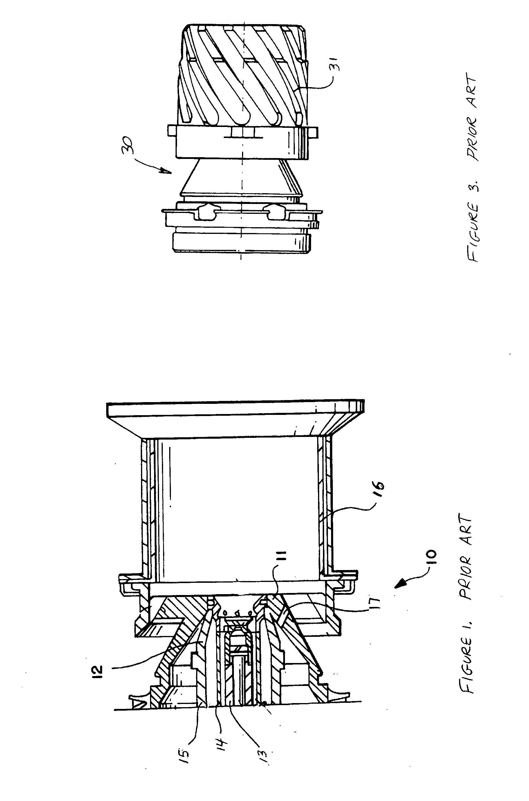
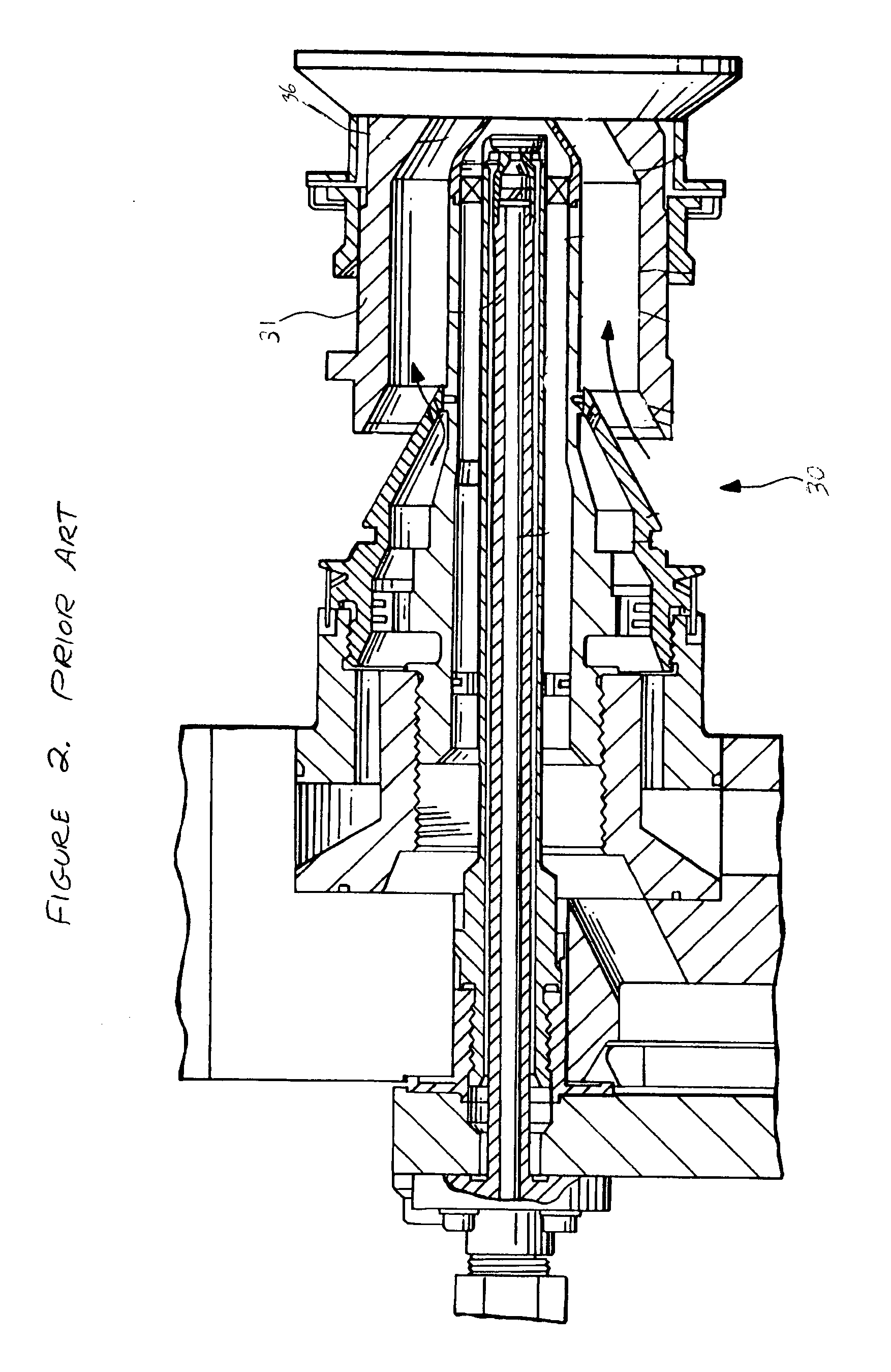
[0006] The present invention improves upon each of the prior art dual fuel nozzles by providing a fuel nozzle designed to reduce carbon buildup while having a relatively simple fuel nozzle configuration. The present invention positions the injection point of the liquid fuel portion approximately halfway in a mixing tube and utilizes a reconfigured spray angle and air swirler and alternate mixing tube to eliminate recirculation areas found in the prior art fuel nozzle.
[0008] The present invention dual fuel nozzle is designed to operate in a gas turbine combustor comprising a combustion liner with a cap assembly fixed to a first end of the combustion liner. The cap assembly has a plurality of openings located about the combustion liner center axis, with each of the openings having a convergent—divergent mixing tube with a forward tube end and aft tube end and a collar positioned adjacent the forward tube end of the mixing tube. The dual fuel nozzles of the present invention are arranged in an annular array about the center liner axis corresponding to the openings in the cap assembly and extend into the mixing tubes to a position approximately halfway between the forward tube end and the aft tube end. Positioning the dual fuel nozzle of the present invention in this location in combination with optimizing the spray orientation of the liquid fuel assembly and reconfigured mixing tube ensures that liquid fuel droplets will not contact the fuel nozzle surface or mixing tube wall, thereby minimizing carbon buildup along said surfaces.
[0009] It is an object of the present invention to provide a gas turbine combustor that can operate on multiple fuel types and exhibit reduced carbon deposits.

Problems solved by technology

While natural gas fired gas turbine engines have become increasingly popular due to lower levels of NOx emissions produced, not all regions of the world in which gas turbine engines operate are regulated by emissions nor is natural gas a desired fuel choice for economic reasons.
More specifically, the combustor hardware surrounding the liquid fuel nozzle has been known to exhibit carbon buildup over a period of time.
Build up of carbon has resulted in poor performance and damage to the fuel nozzles and combustion liner components requiring premature repair and replacement.
Over time, the carbon deposits build-up to a level that impairs fuel nozzle and combustor performance, requiring repair and replacement.

Method used


Image

  • Primary fuel nozzle having dual fuel capability
  • Primary fuel nozzle having dual fuel capability
  • Primary fuel nozzle having dual fuel capability

Examples


Embodiment Construction

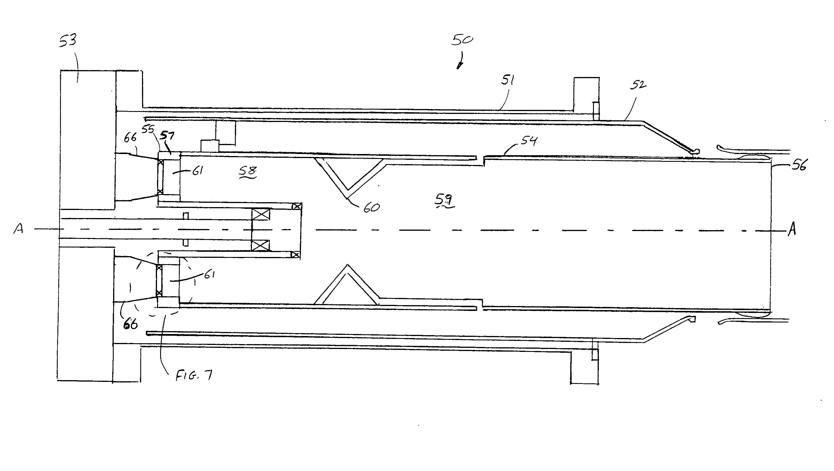
[0019] The present invention is shown in detail in FIGS. 4-7 and is preferably operated in conjunction with a dual stage combustion system such as that shown in FIG. 4. A gas turbine combustor 50 capable of operating on multiple fuels comprises an outer case 51, a sleeve 52, an end cover 53 fixed to a forward end of case 51, and a generally cylindrical combustion liner 54. The combustion liner comprises a first end 55, a second end 56 and a cap assembly 57 fixed to combustion liner 54 proximate first end 55 and located generally within combustion liner 54. Furthermore, combustion liner 54 also comprises a first combustion chamber 58, a second combustion chamber 59, and a venturi 60 separating chambers 58 and 59. Further details of cap assembly 57 can be seen in detail in accordance with FIG. 7. Cap assembly 57 has a plurality of openings 61 located about center line axis A-A, with each of openings 61 having a mixing tube 62 and collar 63. Mixing tube 62 has a forward tube end 64 and...


PUM


Abstract

A fuel nozzle and gas turbine combustor capable of operating on multiple fuels with reduced carbon build-up to the fuel nozzle and adjacent combustor components is disclosed. The fuel nozzle incorporates a reconfigured gas fuel assembly and mixing tube to eliminate known areas of recirculation. Furthermore, the liquid fuel assembly includes reconfigured spray characteristics to further reduce droplet interaction with the mixing tube.

Description

TECHNICAL FIELD [0001] This invention generally relates to gas turbine combustion systems and more specifically to a fuel nozzle having dual fuel capability. BACKGROUND OF THE INVENTION [0002] Land-based gas turbine engines, which are primarily used for generating electricity, include a combustion system that mixes fuel with compressed air from the engine compressor and contains the reaction that generates hot combustion gases to drive a turbine. The combustion system injects a fuel, typically natural gas or a liquid fuel, to mix with the compressed air. Combustion systems which inject either fuel type are typically referred to as dual fuel combustors. This type of combustion system offers flexibility to the engine operator with regard to which fuel to use, depending on fuel availability, fuel costs, and level of emissions allowed. While natural gas fired gas turbine engines have become increasingly popular due to lower levels of NOx emissions produced, not all regions of the world ...

Claims


Application Information

Patent Timeline
IPC IPC(8): F23R3/42
CPCF23R3/16F23R3/283F23R2900/00004F23R3/36F23R3/286
Inventor HENRIQUEZ, JOHNMCLEROY, JACOBMACK, BRIAN R.MARTLING, VINCENT C.
Owner ANSALDO ENERGIA SWITZERLAND AG
Learn More