Method and apparatus for large leak testing
a leak detection and leakage technology, applied in the direction of measuring devices, structural/machine measurement, instruments, etc., can solve the problems of difficult or impossible to reach the required pressure level, the inlet of the mass spectrometer tube must be maintained at a relatively low level, and the vacuum pumping cycle is relatively long. achieve the effect of low reverse flow rate and high reverse flow ra
- Summary
- Abstract
- Description
- Claims
- Application Information
AI Technical Summary
Benefits of technology
Problems solved by technology
Method used
Image
Examples
first embodiment
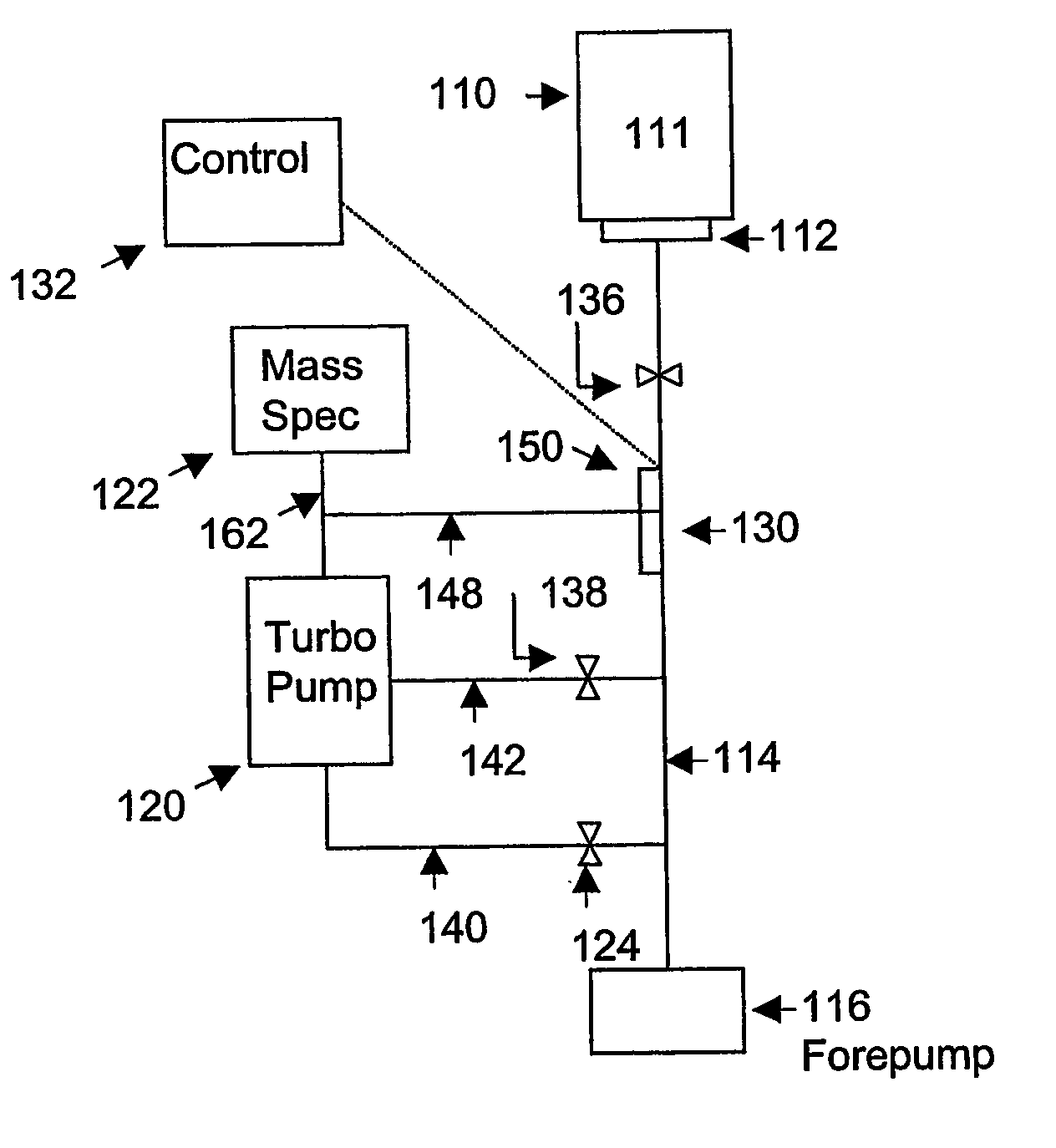
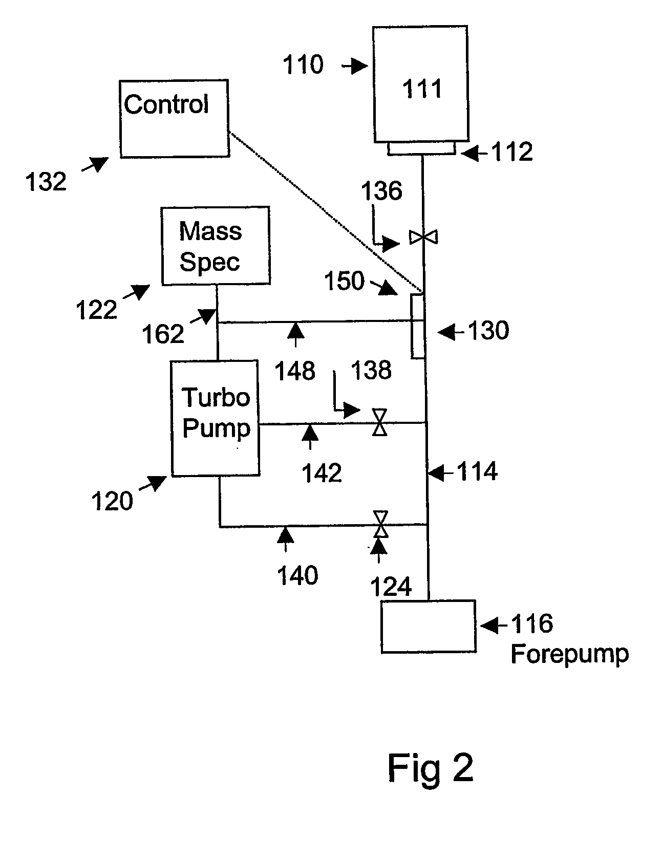
[0024] Apparatus for leak detection in accordance with the invention is shown in FIG. 2. A test piece 110 having a test volume 111 is attached to an inlet flange 112. Inlet flange 112 defines a test port of a leak detector and is connected through a test valve 136 to a test line 114. A forepump 116 has an inlet coupled to test line 114 for pumping of test line 114 and test volume 111. The leak detector further includes a turbopump 120, a mass spectrometer 122, a foreline valve 124, a midstage valve 138, a trace gas permeable member 130, a controller 132 and associated conduits. Mass spectrometer 122 has an inlet 162 coupled to an inlet of vacuum pump 120. A foreline 140 of turbopump 120 is coupled through foreline valve 124 to test line 114. An optional midstage line 142 of turbopump 120 is coupled through midstage valve 138 to test line 114.
[0025] Turbopump 120 may be replaced with a diffusion pump, a so-called hybrid turbopump or a molecular drag pump. A midstage connection is not...
second embodiment
[0032] Apparatus for leak detection in accordance with the invention is shown in FIG. 4. Like elements in FIGS. 2 and 4 have the same reference numerals. In the embodiment of FIG. 4, trace gas permeable member 130 is coupled between test line 114 and foreline 140 of turbopump 120. A bypass valve 160 is coupled between foreline 140 and test line 114. Permeable member 130 is bypassed when valve 160 is open. In operation, helium in test line 114 passes through permeable member 130 to the foreline 140 of turbopump 120. The helium then passes in reverse direction through turbopump 120 to inlet 162 of mass spectrometer 122 and is measured by mass spectrometer 122. In other embodiments, a combination of trace gas permeable member 130 and bypass valve 160 may be connected to midstage line 142 (FIG. 2) of turbopump 120 or may be connected directly to inlet 162 of mass spectrometer 122.
third embodiment
[0033] Apparatus for leak detection in accordance with the invention is shown in FIG. 5A. Like elements in FIGS. 2, 4 and 5A have the same reference numerals. In the embodiment of FIG. 5A, foreline 140 of turbopump 120 is connected to forepump 116, and test line 114 is connected to a separate roughing pump 170. Trace gas permeable member 130 is coupled between inlet 162 of mass spectrometer 122 and test line 114. Bypass valve 160 is coupled in parallel with permeable member 130.
PUM
 Abstract
Description
Claims
Application Information
 - R&D
- Intellectual Property
- Life Sciences
- Materials
- Tech Scout
- Unparalleled Data Quality
- Higher Quality Content
- 60% Fewer Hallucinations
Browse by: Latest US Patents, China's latest patents, Technical Efficacy Thesaurus, Application Domain, Technology Topic, Popular Technical Reports.
© 2025 PatSnap. All rights reserved.Legal|Privacy policy|Modern Slavery Act Transparency Statement|Sitemap|About US| Contact US: help@patsnap.com


