Optical pick-up head, optical information apparatus, and optical information reproducing method

a pickup head and optical information technology, applied in the direction of recording information storage, head disposition/mounting, instruments, etc., can solve the problems of tracking control becoming unstable, large influence of pitch production error amount, and large fluctuation in te signal amplitude, so as to reduce the fluctuation of te signal amplitude and high reliability

Active Publication Date: 2005-09-15
PANASONIC CORP
View PDF5 Cites 64 Cited by
  • Summary
  • Abstract
  • Description
  • Claims
  • Application Information

AI Technical Summary

Benefits of technology

[0013] Therefore, with the foregoing in mind, it is an object of the present invention to provide an optical pick-up head capable of recording / reproducing information with high reliability while reducing fluctuation in a TE signal amplitude, an optical information apparatus, and an information reproducing method.

Problems solved by technology

However, actually, an absolute amount of error is present, so that when a pitch is narrowed, a production error amount with respect to a pitch is relatively increased.
Thus, compared with a DVD, the influence of this error is very large.
As a result, tracking control becomes unstable, and information cannot be recorded / reproduced with high reliability.

Method used


Image

  • Optical pick-up head, optical information apparatus, and optical information reproducing method
  • Optical pick-up head, optical information apparatus, and optical information reproducing method
  • Optical pick-up head, optical information apparatus, and optical information reproducing method

Examples


embodiment 1

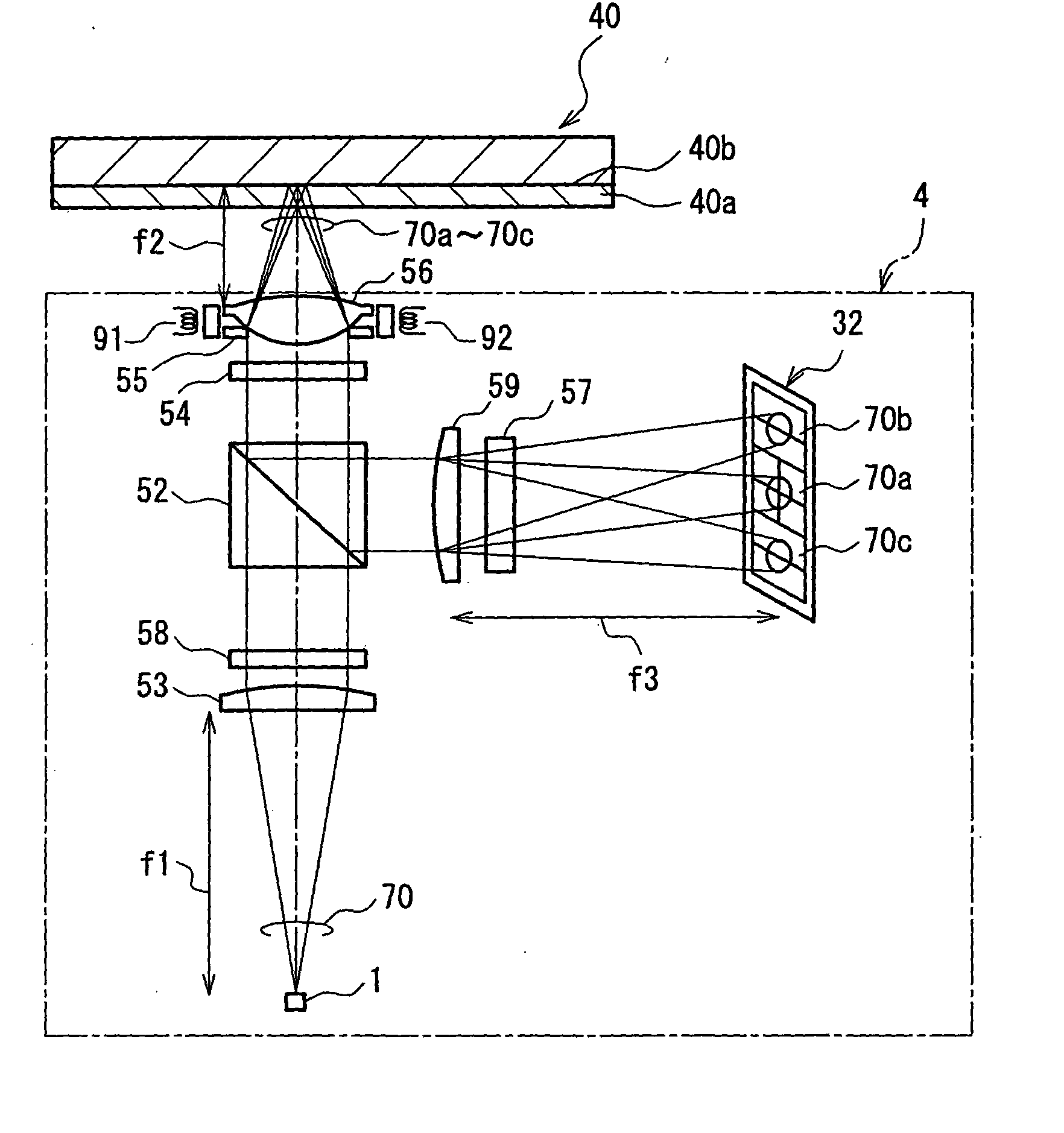
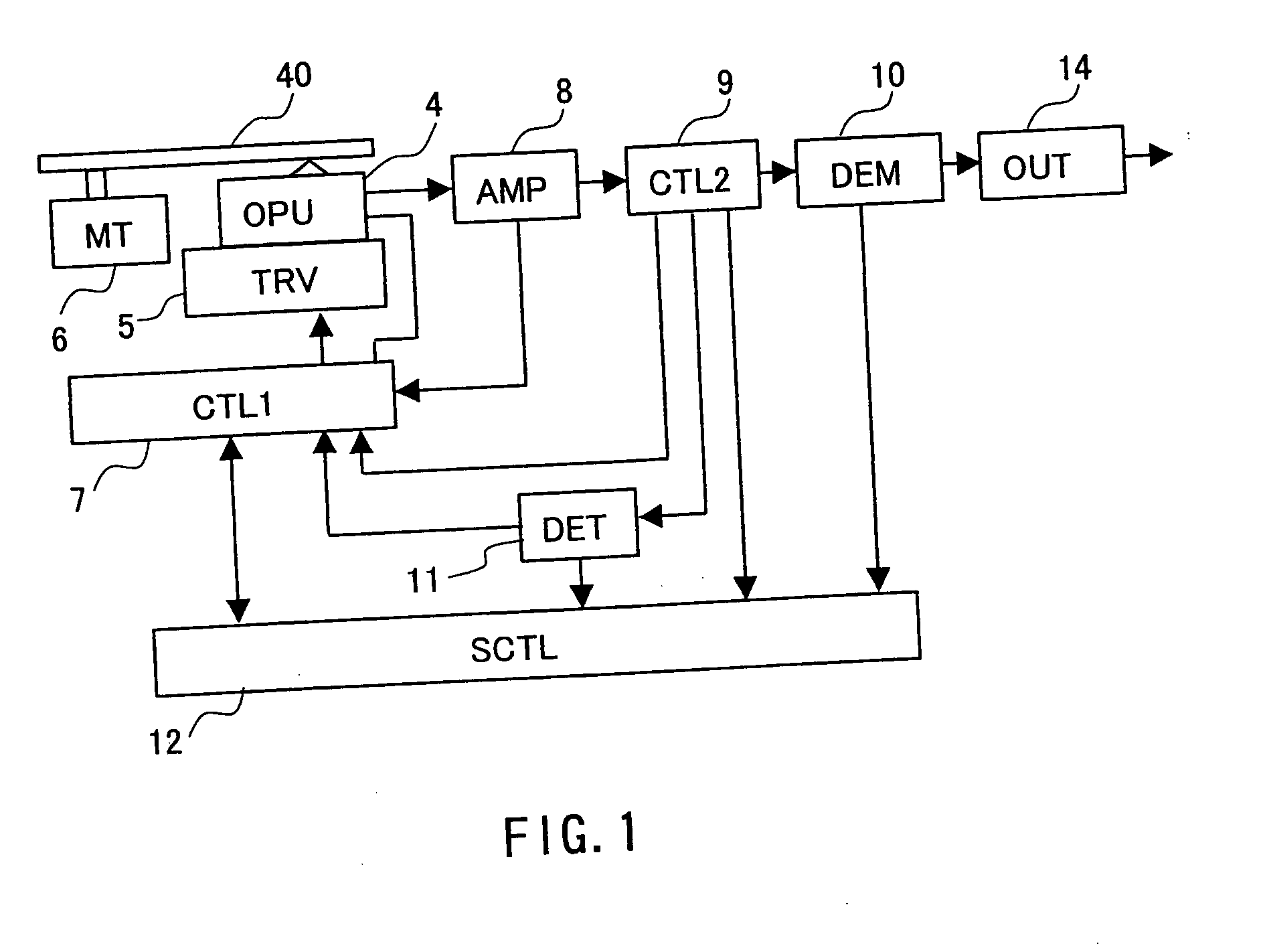
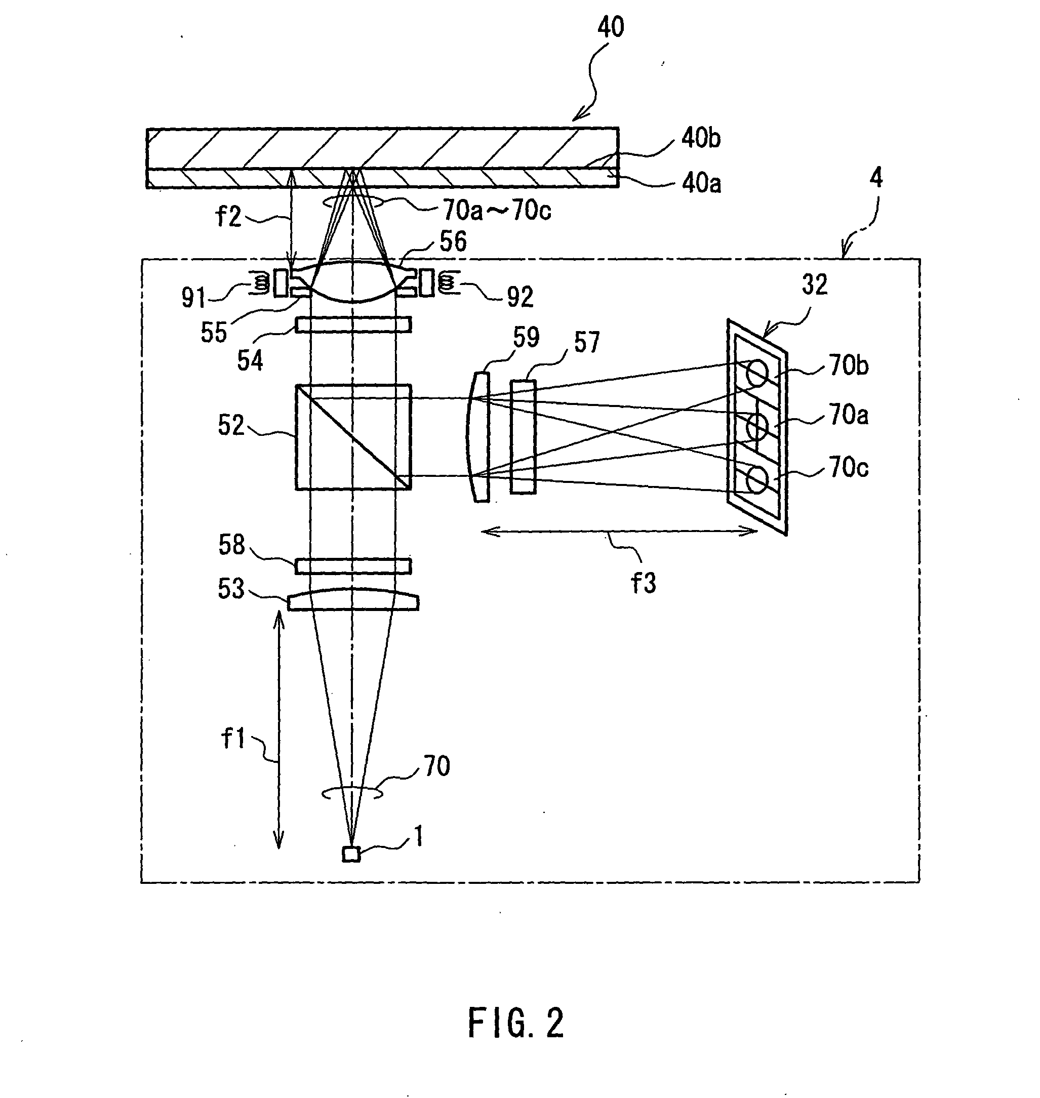
[0166]FIG. 1 shows a configuration of an optical information apparatus of Embodiment 1 according to the present invention. An optical pick-up head 4 irradiates an optical recording medium 40 with laser light having a wavelength λ of 405 nm, thereby reproducing a signal recorded on the optical recording medium 40. A transport controller 5 moves the optical pick-up head 4 in a radius direction of the optical recording medium 40 so as to record / reproduce information at any position on the optical recording medium 40. A motor 6 for driving the optical recording medium 40 rotates the optical recording medium 40. A controller 7 controls the optical pick-up head 4, the transport controller 5, and the motor 6.

[0167] An amplifier 8 amplifies a signal read by the optical pick-up head 4. A controller 9 receives an output signal from the amplifier 8. Based on this signal, the controller 9 generates a servo signal such as a FE (focusing error) signal and a TE (tracking error) signal required fo...

embodiment 2

[0179]FIG. 6 shows a relationship between a beam and a track on the information recording surface 40b as an example of another optical information apparatus according to the present invention. In the optical pick-up head 4 constituting the optical information apparatus of Embodiment 1, when the main beam 70a is positioned on the track Tn, the sub-beam 70c is positioned between the tracks Tn−1 and Tn, and the sub-beam 70b is positioned between the tracks Tn and Tn+1. In the optical pick-up head constituting the optical information apparatus of Embodiment 2, when the main beam 70a is positioned on the track Tn, the sub-beam 70c is positioned between the tracks Tn−2 and Tn−1, and the sub-beam 70b is positioned between the tracks Tn+1 and Tn+2. More specifically, an interval L in a direction orthogonal to the tracks between the main beam and the sub-beams is (3·tp) / 2=0.48 μm. By slightly rotating the diffraction grating 58 in the optical pick-up head 4, an optical pick-up head constitut...

embodiment 3

[0182]FIG. 7 schematically shows a relationship between a photodetector 33 and the beams 70a to 70c as an example of another optical information apparatus according to Embodiment 3. By using the photodetector 33 in place of the photodetector 32 constituting the optical pick-up head 4, an optical information apparatus of Embodiment 3 can be configured. The photodetector 33 has 12 light-receiving portions 33a to 33l in total. The light-receiving portions 33a to 33h receive the beam 70a. The light-receiving portions 33i to 33j receive the beam 70b. The light-receiving portions 33k to 33l receive the beam 70c. The light-receiving portions 33a to 33l output current signals I33a to I33l in accordance with the respectively received light amounts. A FE signal is obtained by the astigmatism method using the current signals I33a to I33h output from the photodetector 33, i.e., by an arithmetic operation (I33a+I33b+I33e+I33f)−(I33c+I33d+I33g+I33h). This arithmetic operation seems to be complica...


PUM

PropertyMeasurementUnit
wavelength λ1aaaaaaaaaa
focal length f1aaaaaaaaaa
focal length f2aaaaaaaaaa

Abstract

An optical information apparatus of the present invention includes: an optical pick-up head including: a light source; a diffraction unit; a condensing unit; a beam splitter; a photodetector; and a tracking error signal generator. An optical recording medium has tracks arranged substantially at a constant pitch. An average of a pitch is tp. When a main beam is placed on the track, a first sub-beam and a second sub-beam are placed between the tracks. The tracking error signal generator performs a differential arithmetic operation with respect to signals output from a light-receiving portion receiving the main beam to generate a first push-pull signal, performs a differential arithmetic operation with respect to signals output from the light-receiving portions receiving the first sub-beam and the second sub-beam to generate a second push-pull signal, and performs a differential arithmetic operation with respect to the first push-pull signal and the second push-pull signal to generate a tracking error signal, in a case where an amplitude of the first push-pull signal obtained at the pitch tp is fluctuated when the light beam is scanned in a direction orthogonal to the tracks of the optical recording medium.

Description

BACKGROUND OF THE INVENTION [0001] 1. Field of the Invention [0002] The present invention relates to an optical pick-up head for recording, reproducing or erasing information with respect to an optical recording medium on which information is recorded with a mark and a space, an optical information apparatus, and an information reproducing method. [0003] 2. Description of the Related Art [0004] Recently, as high-density and large-capacity recording media, high-density and large-capacity optical disks called DVDs have been put into practical use, and spread widely as information media that can deal with a large amount of information such as animation. [0005]FIG. 70 shows a configuration of a general optical system used in an optical pick-up head in an optical disk system as an optical information apparatus capable of recording / reproducing information. According to a conventional configuration, an optical recording medium is irradiated with three light beams to detect a tracking error...

Claims


Application Information

Patent Timeline
Patent Type & Authority Applications(United States)
IPC IPC(8): G11B7/09G11B7/00G11B7/005G11B7/085G11B7/095G11B7/131G11B7/133G11B7/1353G11B7/1381G11B7/1392
CPCG11B7/0901G11B7/0903G11B7/0941G11B7/0943G11B7/0948G11B2007/0013G11B7/133G11B7/1353G11B7/1381G11B7/13927G11B7/131G11B7/005G11B7/09
Inventor KADOWAKI, SHIN-ICHISANO, KOUSEIARAI, AKIHIROYASUDA, KATSUHIKOKAMEI, TOMOTADAYAMAMOTO, HIROAKIYAMASAKI, FUMITOMO
Owner PANASONIC CORP
Why Eureka
Try Eureka