

EUV light source
a technology of euv light and collector, which is applied in the field of euv light generation, can solve the problems of ineffective generation of euv light, unwanted and damaging depositions in the lpp euv chamber, and it is more difficult to remove impurities from the collector, and achieves the effect of sufficient size and thermal mass
- Summary
- Abstract
- Description
- Claims
- Application Information
AI Technical Summary
Benefits of technology
Problems solved by technology
Method used
Image

Examples
Embodiment Construction
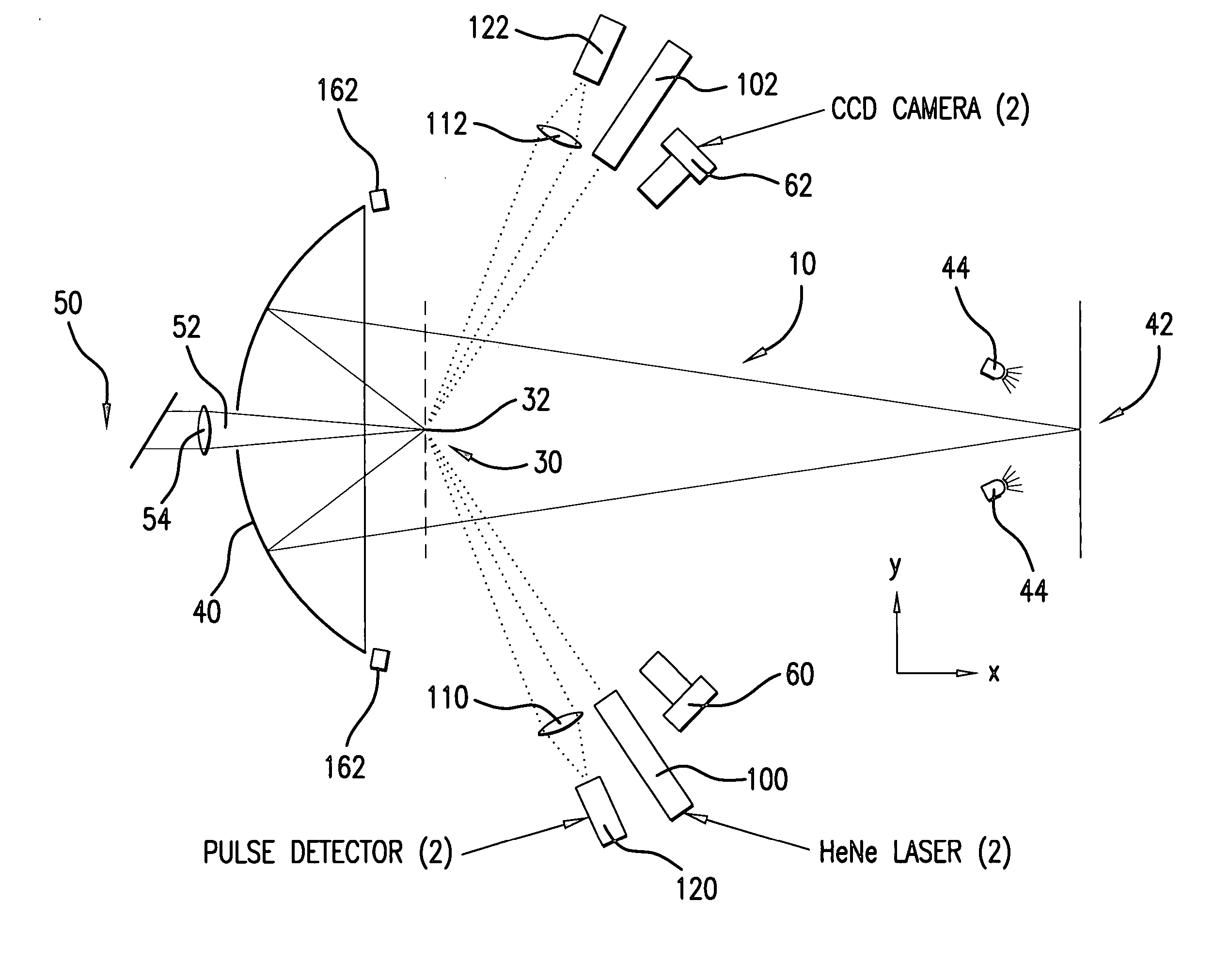
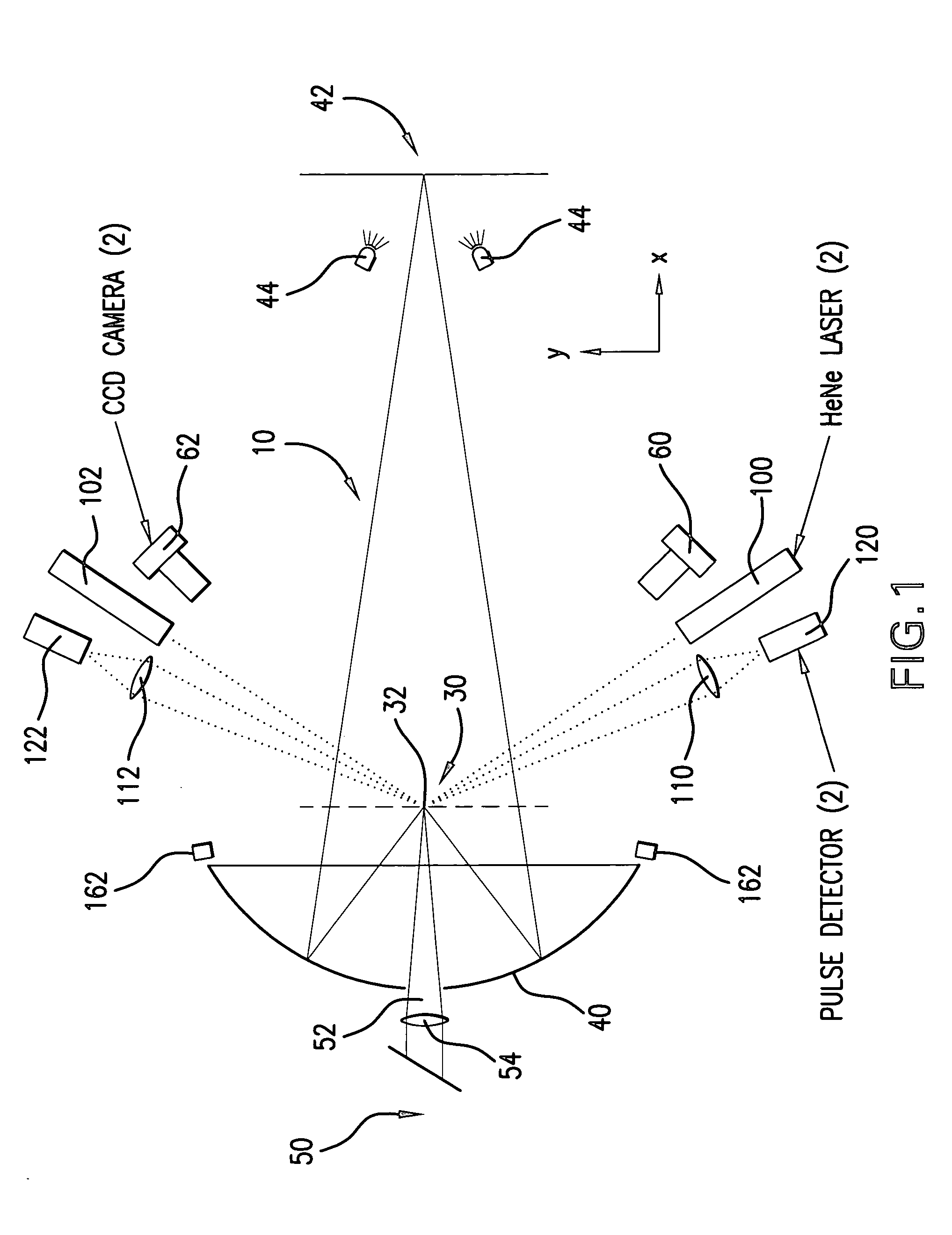
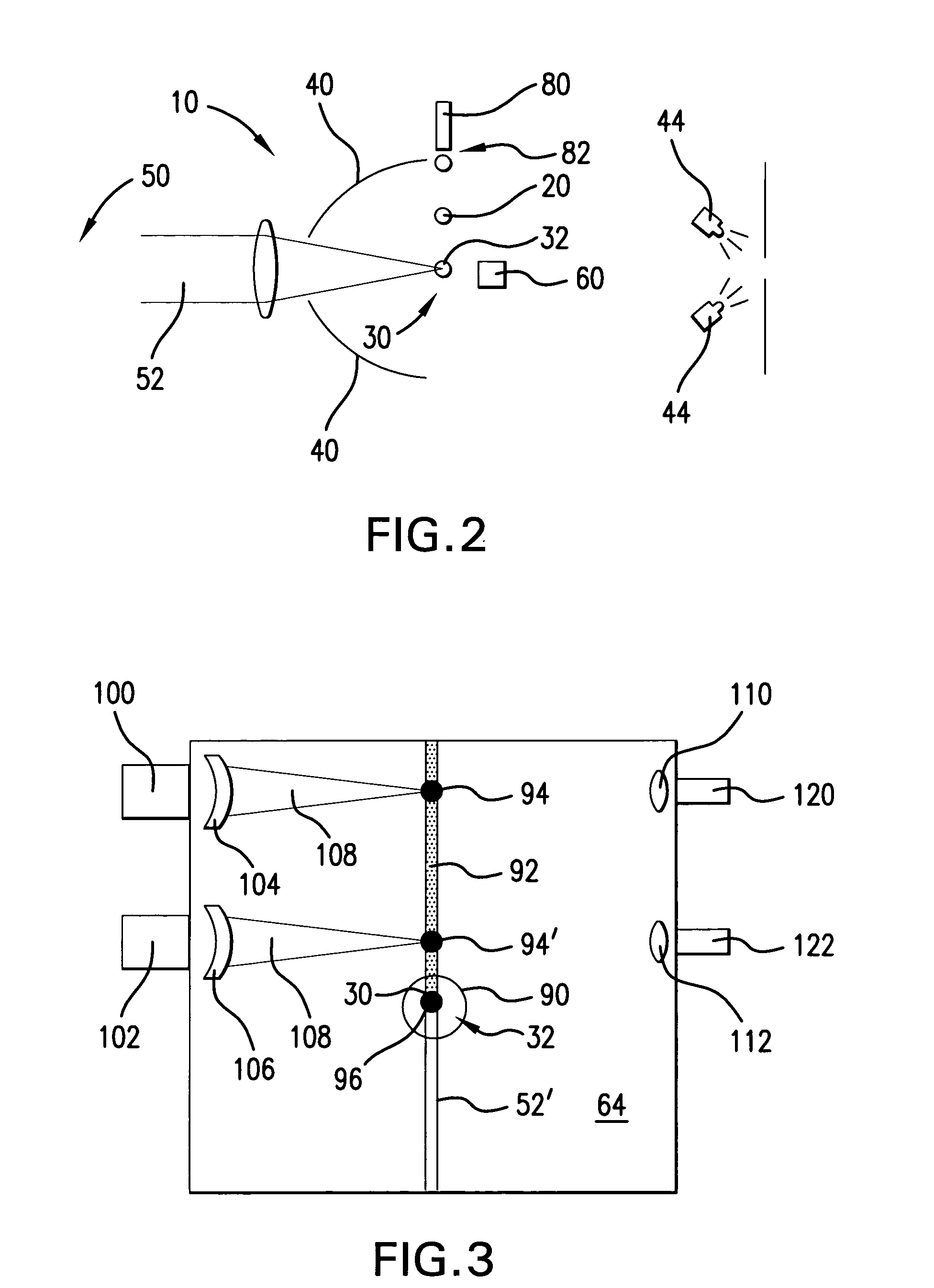
[0029] According to aspects of an embodiment of the present invention, Applicants propose portions of an EUV light source system 10, illustrated schematically in FIG. 1, that is capable of aspects of active control of the position, pointing and focusing of an EUV plasma initiation drive laser(s) and pre-pulse laser(s) directed at a target, e.g., in a plasma formation / EUV source chamber 64 (not shown in FIG. 1), e.g., a moving droplet (20, as shown in FIG. 2) of liquid metal, e.g., lithium, which may be mass limited.
[0030] Some general requirements according to aspects of an embodiment of the present invention include the need to collect as much EUV light from the LPP as possible according to which applicants presently contemplate a need for about a 5 sr solid angle for collection of the plasma produced EUV light. In addition, contemplated is to provide a matching angle to the illuminator with a need for the correct solid angle for acceptance at the intermediate focus 42 (“IF”), e.g...
PUM
 Abstract
Description
Claims
Application Information