Multi-channel induction accelerator

Inactive Publication Date: 2005-09-15
VIARA RES
View PDF0 Cites 3 Cited by
  • Summary
  • Abstract
  • Description
  • Claims
  • Application Information

AI Technical Summary

Benefits of technology

[0015] This device (the MIAC) is most similar to the invention proposed with respect to the technological essence and result achieved. This device is accepted as a

Problems solved by technology

This means that in the case of the 50-MeV system its total length is ˜70 m. This causes strong complications in overall infrastructure and its accommodation and service (because it needs special accommodation, radiation-protection systems and service, etc.).
Consequently, commercial application of OILINAC as a basic construction element for various types of commercial devices becomes economically unsuitable because of their excessive price.
A direct use of the OILINAC in such situations is impossible, since, as it was mentioned before, they are designed for the formation of exclusively one-energy and one-component relativistic beams of charged particles.
This means that OILINAC possesses limited functional possibilities with respect to potential fields of application.
It is well known that the limita

Method used


Image

  • Multi-channel induction accelerator
  • Multi-channel induction accelerator
  • Multi-channel induction accelerator

Examples


Embodiment Construction

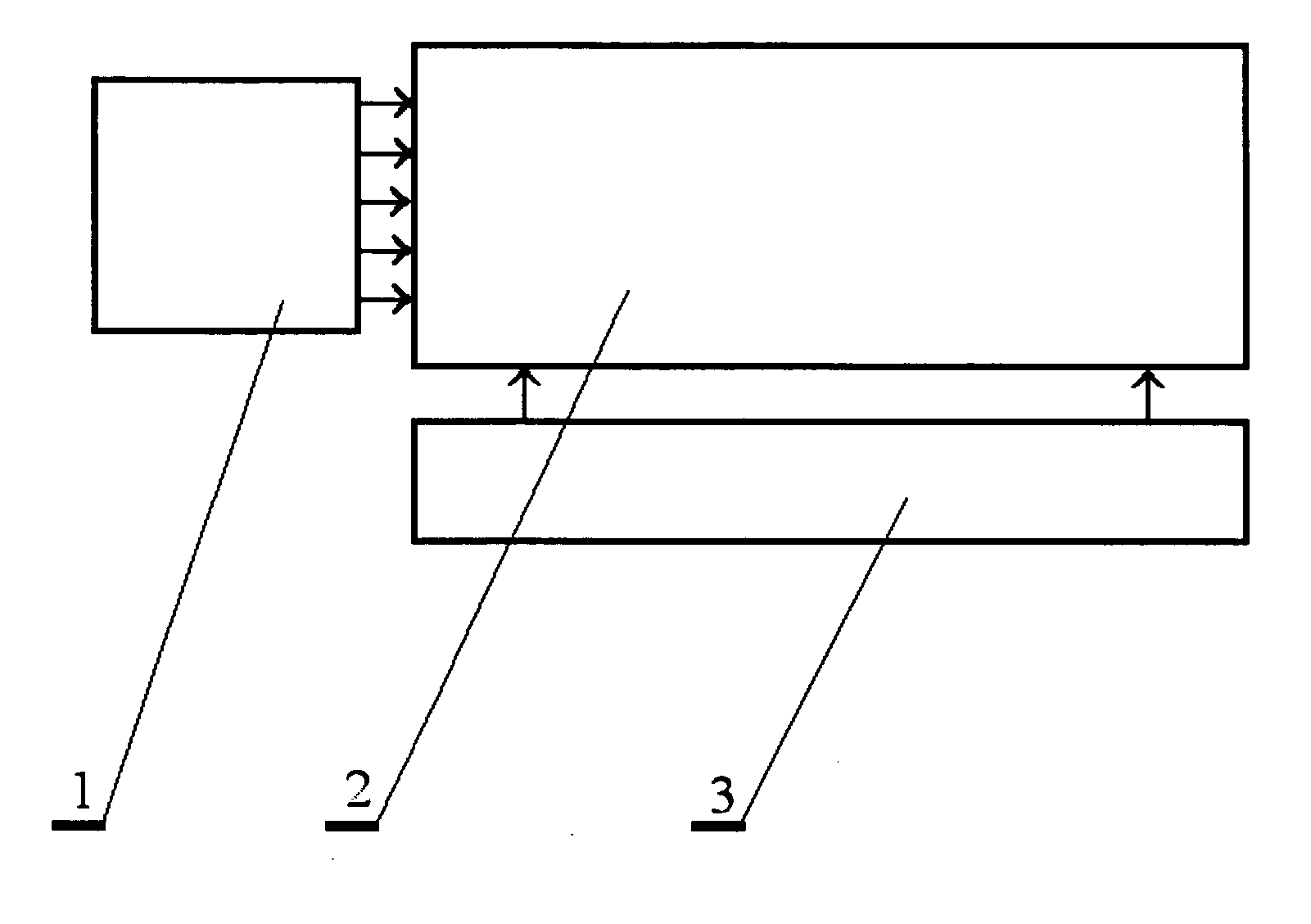
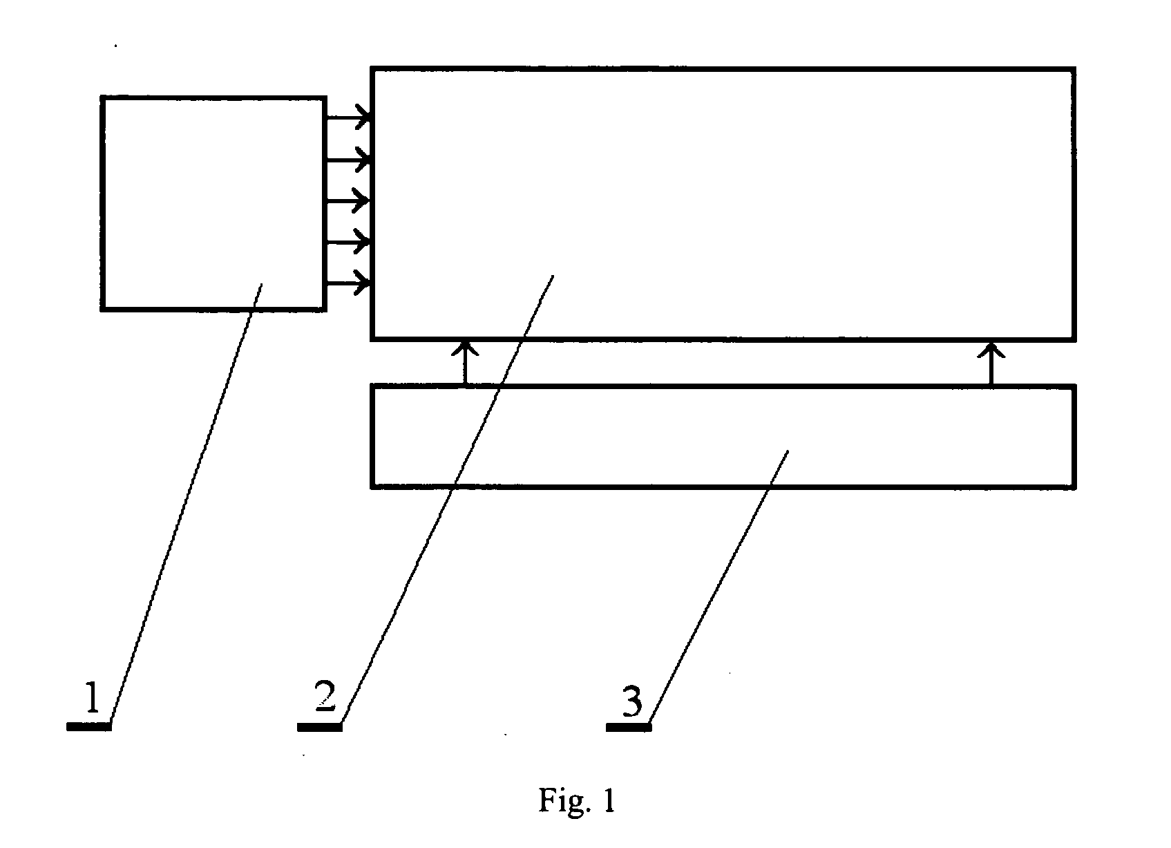
[0031] The multi-channel induction accelerator (MIAC, see FIG. 1) comprises an injector block 1, which is attached to a multi-channel induction acceleration block 2. A drive source 3 is attached, at the same time, to the block 1. The output systems here are included conditionally into the multi-channel induction acceleration block 1. The injector block is made in the form of separate or an aggregate of separate electron and ion injectors.

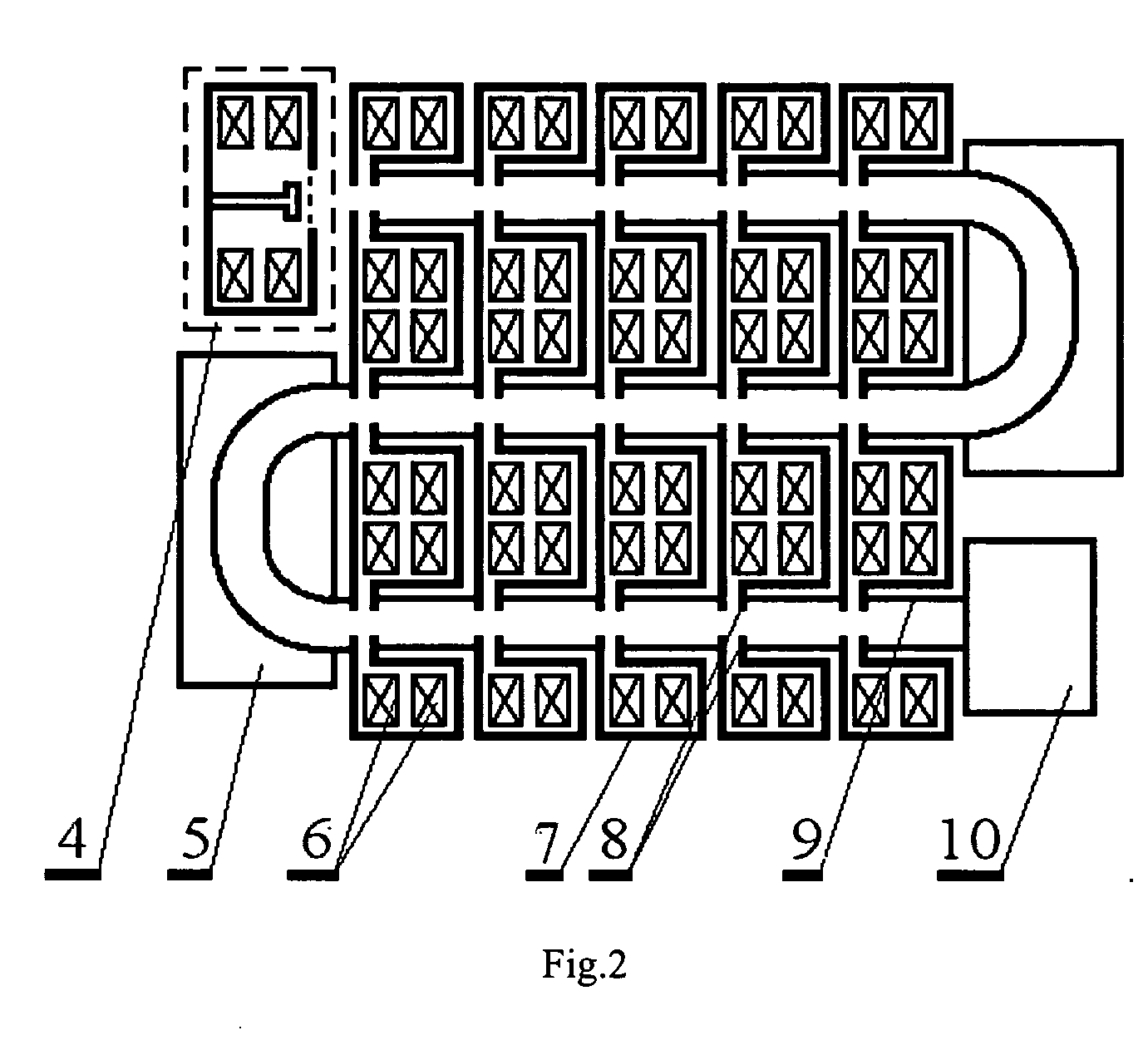
[0032] The design example of the MIAC, constructed on the basis of the MIUNAC, is shown in FIG. 2. There 4 is the injector of the block 1, 5 are the turning systems for the charged particle beam, 6 are the magnetic inductors of the acceleration sections, 7 are the conductive screens, 8 are the accelerative spaces in the undulative acceleration channel 9, 10 is the output system. The multi-channel induction acceleration block 2 is made in the form of three parallel placed one-channel induction acceleration blocks, each of which, in turn, is construc...


PUM


Abstract

A multi-channel induction accelerator (MIAC) comprised of the injector block, the drive source, the output device, and the multi-channel induction acceleration block. The latter is made in the form of an aggregate of one-channel linear induction acceleration blocks (including those which are oriented parallel one to other), each of which is made in the form of a sequence of the linearly connected acceleration sections, each of which, in turn, is made in the form of one or a few magnetic inductors enveloped by a conductive screen. Therein, at least one of the conductive screens is made in such a manner that it envelops at least two acceleration sections, which belong to different one-channel linear induction acceleration blocks. The invention allows to increase electric voltage in acceleration spaces of the acceleration sections without increasing the current strength in the inductors winding, and to increase efficiency of the accelerator.

Description

CROSS-REFERENCE TO RELATED APPLICATIONS STATEMENT REGARDING FEDERALLY SPONSORED RESEARCH [0001] Not applicable. BACKGROUND OF THE INVENTION [0002] The invention concerns acceleration engineering, and is especially addressed to induction accelerators. It has application as a commercial-type compact powerful accelerator of charged particles for the formation of relativistic beams of charged particles and for systems of many parallel multi-component beams. [0003] There is known an induction accelerator, which can be used as a device for the formation of singular electronic relativistic beams Redinato L. “The advanced test accelerator (ATA), a 50-MeV, 10-kA Inductional Linac.” IEEE Trans.,NS-30, No 4, pp. 2970-2973, 1983. This device also is called a one-channel linear induction accelerator (OILINAC). The OILINAC is composed of the injector block, the drive source, output system, and a one-channel linear induction acceleration block. Its peculiarity is that the one-channel linear induct...

Claims


Application Information

Patent Timeline
IPC IPC(8): H01J25/50
CPCH05H9/00
Inventor KULISH, VICTOR V.MELNYK, ALEXANDRIA C.LANDGRAF, ALECK K.
Owner VIARA RES
Why Eureka
Try Eureka