Audio signal amplification method and apparatus

a technology of audio signal and amplifier, applied in the direction of amplifier, dc amplifier with modulator-demodulator, semiconductor device/discharge tube, etc., can solve the problems of reducing the power efficiency of the amplifier, lc filter is bulky, and occupying a larger space, so as to reduce power consumption, eliminate noise, and prolong the operation time of such batteries

Inactive Publication Date: 2005-09-15
DIGIAN TECH
View PDF5 Cites 19 Cited by
  • Summary
  • Abstract
  • Description
  • Claims
  • Application Information

AI Technical Summary

Benefits of technology

[0017] Also, the audio signal amplification apparatus according to the present invention is an amplifier including a ΔΣ converter for compressing an M-bit digital audio data into an N-bit audio output data, a pulse width modulator for pulse width modulating the output data from the ΔΣ converter, and a driver control circuit for controlling the bridge configuration driverunit which drives a load such as a speaker or the like by the 1-bit output from the pulse width modulator, characterized in the provision of a low pass filter at the output side of the ΔΣ converter for converting the N-bit output data from the ΔΣ converter into an L-bit output data. According to a preferred embodiment of the present invention, a delay device is interposed between the pulse width modulator and the driver control circuit. The delay element is inserted into only one side of the two outputs lines from the pulse width modulator. The delay device is Z−n, wherein n is set to any integer with the inverse of the sampling frequency being 1. The delay device comprises D-type flip-flop circuits. The low pass filter eliminates any noise outside of the audible frequency band which is generated by the ΔΣ converter. The low pass filter comprises a plurality of cascade connected delay devices and a plurality of adders for sequentially adding the output from each delay device with a preset filter coefficient.
[0018] The audio signal amplification method and apparatus according to the present invention exhibit the following significant practical advantages. That is, it is possible to directly connect a load such as a speaker or the like to the driver unit (i.e., without interposing a low pass filter such as an LC filter). Elimination of inductors occupying a large space helps to achieve miniaturization, thereby making it possible to provide a miniaturized and light-weight output stage amplifier which is essential and suitable to, for example, hearing aids. In addition, elimination of inductors essentially accompanying resistive components suppresses power consumption, which is particularly important in portable electronic apparatus having built-in batteries because the operation time of such batteries can be extended.

Problems solved by technology

Unfortunately, since the low pass filter LPF connected in front of the speaker SP is bulky as compared to active devices or IC devices such as transistors, thereby occupying a larger space, which is disadvantageous as an output amplifier for compact electronic apparatus, for example, a hearing aid or the like.
Additionally, LC filters, in particular inductors accompany with resistive components, which decrease power efficiency of the amplifier.
Such LC filter is bulky and consumes a large power by the resistive components at the front stage of the speaker in which a large current flows, thereby making it difficult to achieve high efficiency.

Method used


Image

  • Audio signal amplification method and apparatus
  • Audio signal amplification method and apparatus
  • Audio signal amplification method and apparatus

Examples


Embodiment Construction

[0027] Now, a preferred embodiment of the audio signal amplification method and apparatus according to the present invention will be described in detail both in construction and operation by making reference to the accompanying drawings.

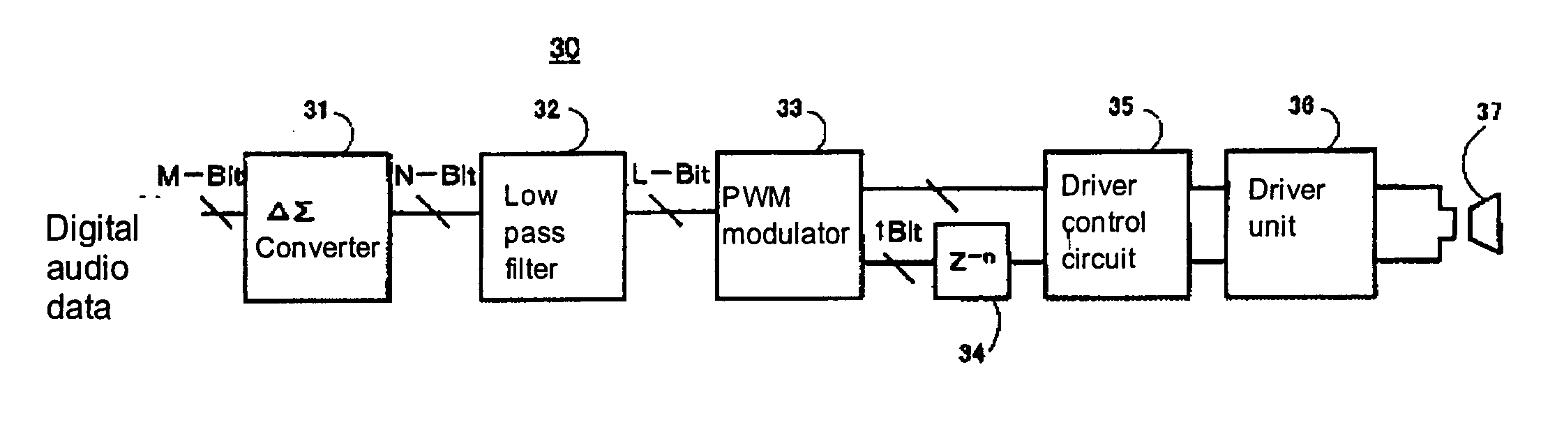
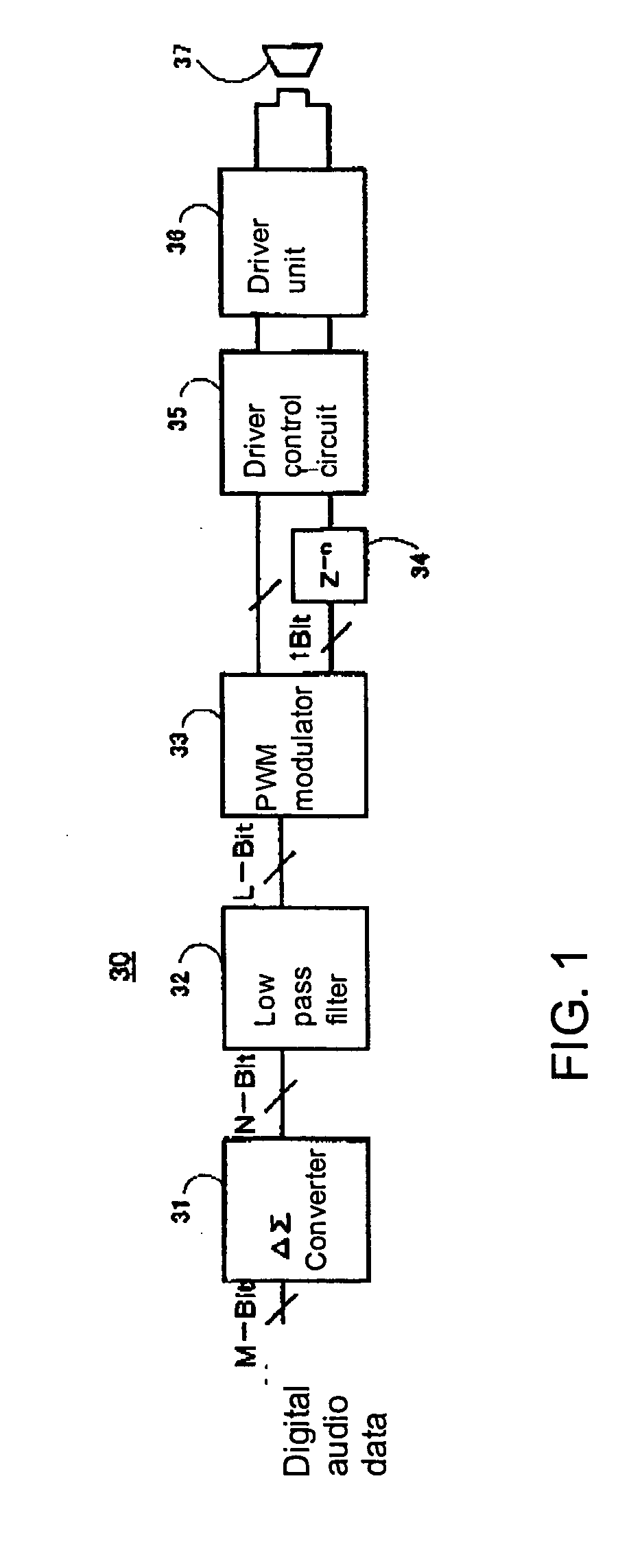
[0028] Firstly, FIG. 1 is a block diagram to show the basic construction of a preferred embodiment of the audio signal amplification apparatus according to the present invention. The audio signal amplification apparatus 30 comprises a delta-sigma (ΔΣ) converter 31, a low pass filter 32, a pulse width modulator 33, a delay device 34, a driver control circuit 35 and a driver unit 36 which are connected in a cascade manner. A speaker 37 is directly connected to the driver unit 36 as a load.

[0029] It is to be noted herein that the digital audio data to be inputted to the ΔΣ converter 31 is any digital audio data from digital audio sources such as, for example, CDs, MDs or DVDs or any digital audio data which is any analog audio signal from FM / AM radio ...


PUM


Abstract

In order to provide an audio signal amplification method and apparatus capable of directly connecting a load such as a speaker to a driver unit of a class-D amplifier without an LC filter, an output data from a ΔΣ converter 31 for compressing a digital audio data from a digital audio source is applied to a pulse width modulator 33 by way of a low pass filter 32 and a driver unit is controlled by a driver control circuit 35 by way of a delay device 34. A speaker 37 as a load is directly driven by P output and N output from the driver unit 36.

Description

FIELD OF THE INVENTION [0001] The present invention relates to an audio signal amplification method and apparatus, more specifically to a digital audio signal amplification method and apparatus for power amplifying a digital audio signal in order to drive a load such as a speaker or the like. BACKGROUND ART [0002] Audio signals are supplied from various sources including, for example, FM / AM radio receivers, digital audio sources prerecorded on CDs (compact discs), MDs (mini-discs), DVDs (digital versatile discs), etc., or analog audio sources prerecorded on audio magnetic tapes (or cassette tapes) or microphones of “karaoke” systems. It is common that users select an audio signal from such various audio signal sources depending on their choice and amplifies such selected audio signal by amplifier means in an audio system or the like before driving a load such as a speaker, a headphone or an earphone as an electro-acoustic converter. [0003] Various amplifiers (or amplifier circuits) ...

Claims


Application Information

Patent Timeline
Patent Type & Authority Applications(United States)
IPC IPC(8): H03F3/217H03F3/38
CPCH03F3/217
Inventor SHINOHARA, YOSHIAKIOGAWA, HIROYOSHI
Owner DIGIAN TECH
Why Eureka
Try Eureka