Method and apparatus for providing real-time calculation and display of tissue deformation in ultrasound imaging

Inactive Publication Date: 2005-09-15
G E VINGMED ULTRASOUND
View PDF26 Cites 52 Cited by
  • Summary
  • Abstract
  • Description
  • Claims
  • Application Information

AI Technical Summary

Benefits of technology

[0031] According to another aspect of a preferred embodiment of the present invention, tissue velocity is estimated in a manner that reduces aliasing while maintaining spatial resolution. Three copies of a received ultrasound signal are bandpass filtered at three center frequencies. The middle of the three center frequencies

Problems solved by technology

One disadvantage of estimating image deformation based on correlation of images is that the instantaneous value of the strain is not calculated nor displayed in real-time.
The lack of a real-time capability is an important clinical disadvantage.
However, the method described in the Kanai et al. article has the disadvantages of poor temporal resolution and high computational cost, which render real-time imaging difficult and costly.
Furthermore, the method described in the Kanai et al. article is a manual M-mode technique, not well suited to form the basis for real-time two-dimensional strain images.
Also, the strain velocity is a derivative of a velocity estimate and is therefore very noise sensi

Method used


Image

  • Method and apparatus for providing real-time calculation and display of tissue deformation in ultrasound imaging
  • Method and apparatus for providing real-time calculation and display of tissue deformation in ultrasound imaging
  • Method and apparatus for providing real-time calculation and display of tissue deformation in ultrasound imaging

Examples


Example

[0048] A method and apparatus are described for generating diagnostic images of tissue deformation parameters, such as strain rate, strain and tissue velocity, in real time and / or in a post processing mode. In the following description, numerous specific details are set forth in order to provide a thorough understanding of the preferred embodiments of the present invention. It will be apparent, however, to one of ordinary skill in the art that the present invention may be practiced without these specific details.

[0049] A block diagram for an ultrasound imaging system according to a preferred embodiment of the present invention is shown in FIG. 3. A transmitter 140 drives an ultrasonic transducer 142 to emit a pulsed ultrasonic beam 144 into the body. The ultrasonic pulses are backscattered from structures in the body, like muscular tissue, to produce echoes which return to and are detected by the transducer 142. A receiver 146 detects the echoes. The echoes are passed from the rece...


PUM


Abstract

An 
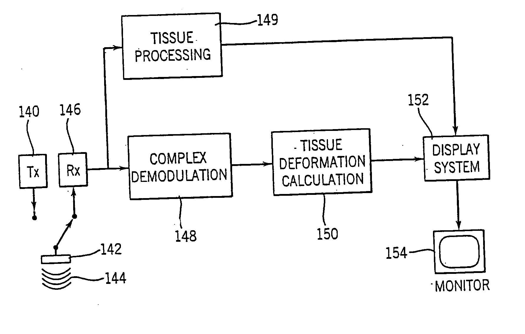
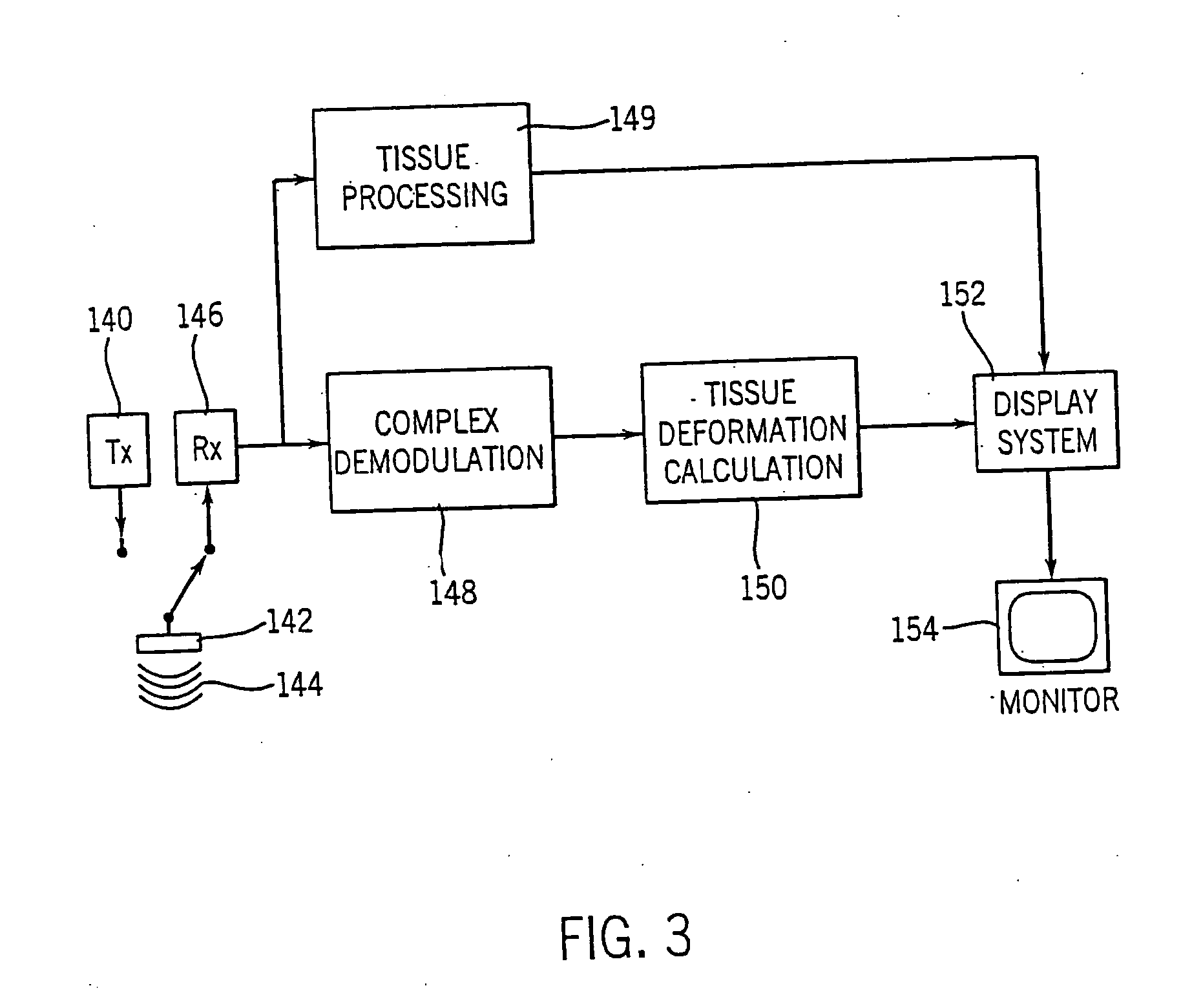
ultrasound system and method for calculation and display of tissue deformation parameters are disclosed. An 
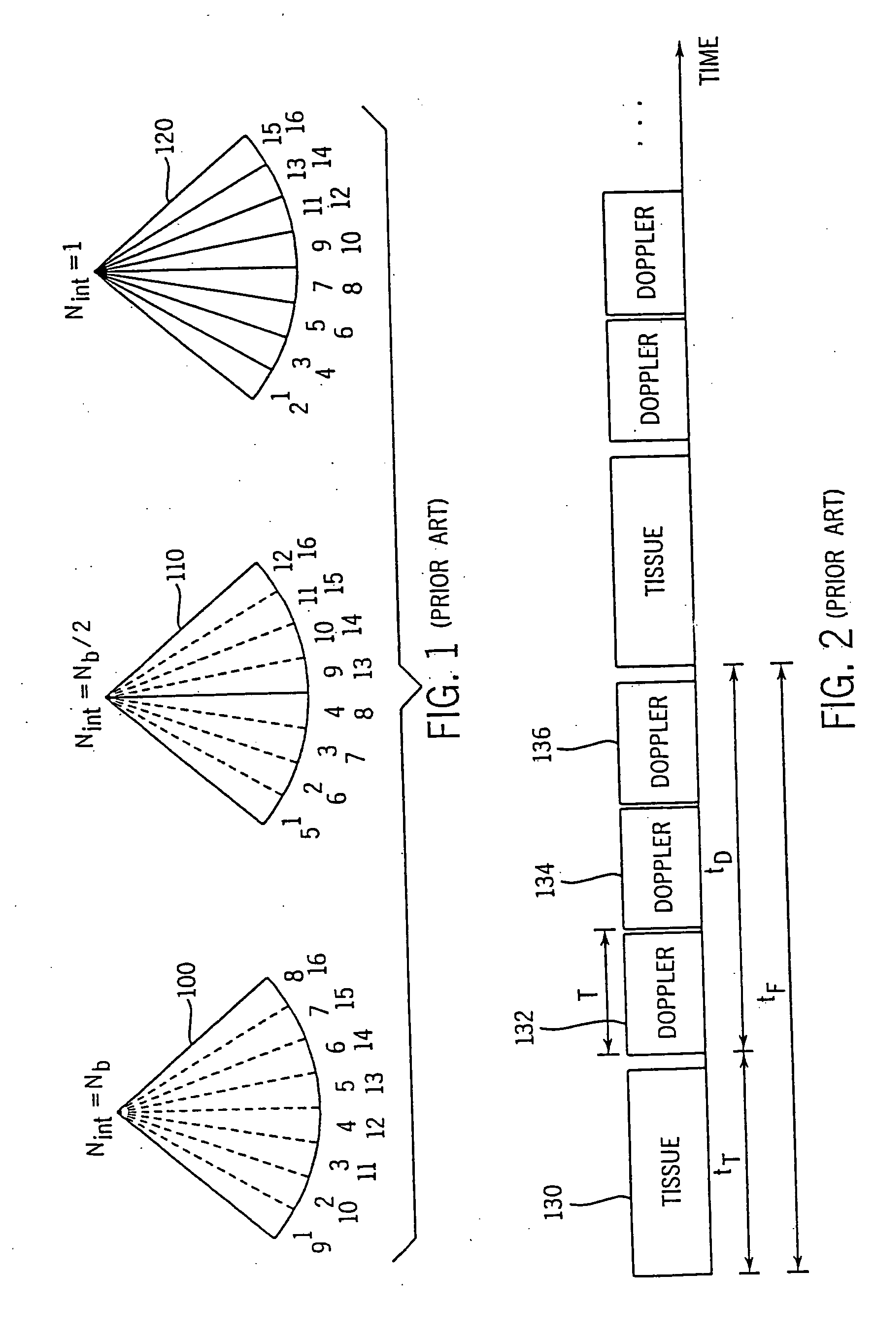
ultrasound acquisition technique that allows a high frame rate in tissue velocity imaging or strain rate imaging is employed. With this acquisition technique the same ultrasound pulses are used for the tissue image and the Doppler based image. A sliding window technique is used for processing. The tissue deformation parameter strain is also determined by an accumulation of strain rate estimates for consecutive frames over an interval. The interval may be a triggered interval generated by, for example, an R-wave in an ECG trace. The strain calculation may be improved by moving the sample volume from which the strain rate is accumulated from frame-to-frame according to the relative displacement of the tissue within the original sample volume. The relative displacement of the tissue is determined by the instantaneous tissue velocity of the sample volume. An estimation of strain rate based upon a spatial derivative of tissue velocity is improved by adaptively varying the spatial offset, dr. The spatial offset, dr, can be maximized to cover the entire tissue segment (e.g., heart wall width) while still keeping both of the sample volumes at each end of the offset within the tissue segment. This may be accomplished by determining whether various parameters (e.g., grayscale value, absolute power estimate, magnitude of the autocorrelation function with unity temporal lag and/or magnitude of strain correlation) of the sample volumes within in the spatial offset are above a given threshold. Strain rate may be estimated using a generalized strain rate estimator that is based on a weighted sum of two-sample strain rate estimators with different spatial offsets. The weights are proportional to the magnitude of the strain rate correlation estimate for each spatial offset, and thus reduce the effect of noisy, i.e. poorly correlated, samples. An improved signal correlation estimator that uses a spatial lag in addition to the usual temporal lag is disclosed. The spatial lag is found from the tissue velocity. The improved signal correlation estimator can be utilized both in the estimation of strain rate and tissue velocity. Tissue velocity may be estimated in a manner that reduces aliasing while maintaining spatial resolution. Three copies of a received ultrasound signal are bandpass filtered at three center frequencies. The middle of the three center frequencies is centered at the second harmonic of the ultrasound signal. A reference tissue velocity is estimated from the two signals filtered at the outside center frequencies. The reference tissue velocity is used to choose a tissue velocity from a number of tissue velocities estimated from the signal centered at the second harmonic. A method to estimate the strain rate in any direction, not necessarily along the ultrasound beam, based on tissue velocity data from a small region of interest around a sample volume is disclosed. Quantitative tissue deformation parameters, such as tissue velocity, tissue velocity integrals, strain rate and/or strain, may be presented as functions of time and/or spatial position for applications such as stress echo. For example, strain rate or strain values for three different stress levels may be plotted together with respect to time over a cardiac cycle. Parameters which are derived from strain rate or strain velocity, such as peak systolic wall thickening percentage, may be plotted with respect to various stress levels,

Description

CROSS REFERENCE TO RELATED APPLICATIONS [0001] This application is a Divisional Application of U.S. patent application Ser. No. 09 / 432,061, filed Nov. 2, 1999, now pending, which is based upon U.S. Provisional Application No. 60 / 150,264, filed Aug. 23, 1999.STATEMENT REGARDING FEDERALLY SPONSORED RESEARCH & DEVELOPMENT [0002] (if applicable) BACKGROUND OF THE INVENTION [0003] The present invention relates to diagnostic ultrasound systems which measure and image anatomical structures, and their movement. More particularly, the present invention relates to a signal processing method and apparatus for calculation and display of tissue deformation to be used in ultrasonic imaging systems. [0004] Recently, within the field of ultrasound imaging, physicians have become interested in using tissue deformation properties, such as tissue strain and strain velocity for clinical measurements. [0005] The term “strain” refers to a characteristic of material being examined. For example, the strain...

Claims


Application Information

Patent Timeline
IPC IPC(8): A61B5/352A61B8/13A61B8/08G01S7/52G01S15/58G01S15/89
CPCA61B5/0456A61B8/485A61B8/488A61B8/543G01S7/52036G01S7/52038A61B5/7239G01S7/52057G01S7/52085G01S7/52095G01S15/584G01S15/8979G01S7/52042A61B5/352A61B8/13
Inventor TORP, HANSOLSTAD, BJORNHEIMDAL, ANDREASBJAERUM, STEINAR
Owner G E VINGMED ULTRASOUND
Why Eureka
Try Eureka