Stenosis detection device

a detection device and stenosis technology, applied in the field of stenosis detection devices, can solve the problems of invasive methods, risk to patients, and major and very costly treatment of coronary stenosis

Inactive Publication Date: 2005-09-15
IMPEDANCE VASCULAR IMAGING PROD
View PDF22 Cites 8 Cited by
  • Summary
  • Abstract
  • Description
  • Claims
  • Application Information

AI Technical Summary

Benefits of technology

[0012] Thus a relatively simple device is provided, which may be used without supervision by a physician, and the function of which which may be easily automated.
[0049] In an advantageous method according to the invention, the plurality of measuring electrodes covers the heart substantially completely. It then becomes possible to cover and measure the heart in one step, or at least a drastically reduced number of steps, instead of applying the electrodes to measure one region of the heart, and thereafter the next, and so on. This greatly reduces fiddling with the patient, which also helps to reduce stress in the patient, and hence variations in the blood flow.

Problems solved by technology

The treatment of coronary stenosis is a major and very costly part of health care.
Some of the methods are invasive.
These invasive methods require the presence of a doctor, and are a risk to the patient.
Most such non-invasive methods require the use of bulky and costly machines, e.g. MRI-apparatus.
These methods are not suitable for wide spread use in physicians' practices, or travelling doctors etc.
Fast CT-scans are a new non-invasive method, but it is limited by poor detection of soft plaque.
However, it is necessary to use a separate device to determine a time gate in which the heart itself is not moving, which would cause additional measuring error.
Furthermore, this method only allows a 2-dimensional section to be measured, and hence necessitates active aiming and scanning across the heart, which is hardly possible to automate.

Method used


Image

  • Stenosis detection device
  • Stenosis detection device
  • Stenosis detection device

Examples


Embodiment Construction

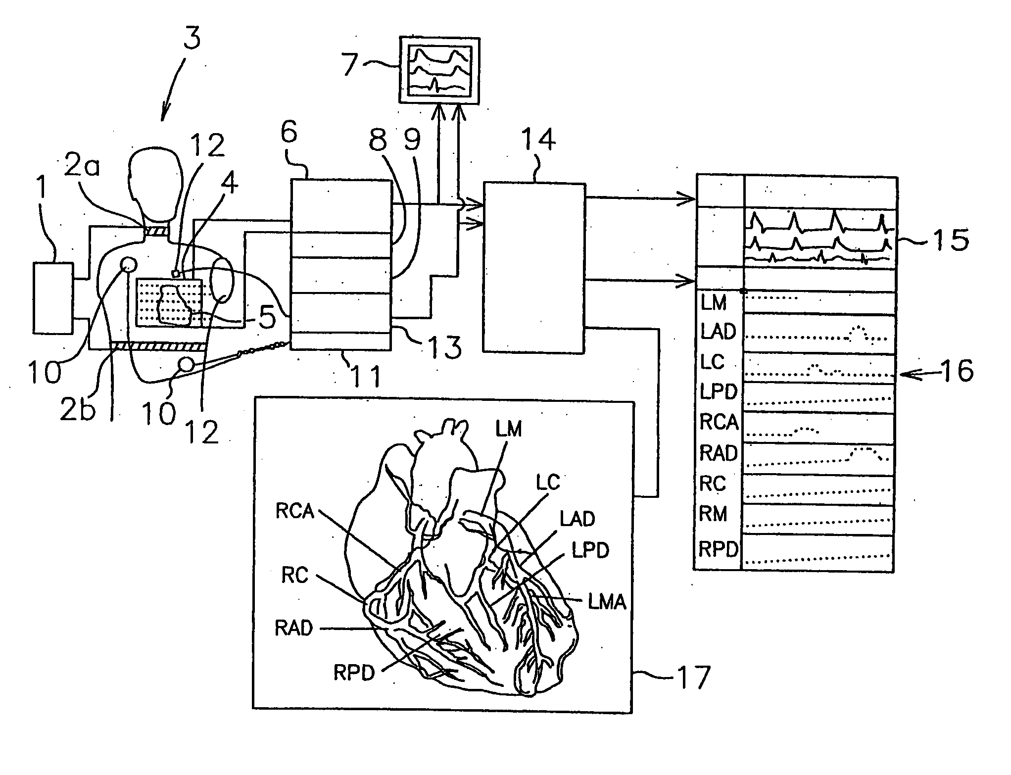
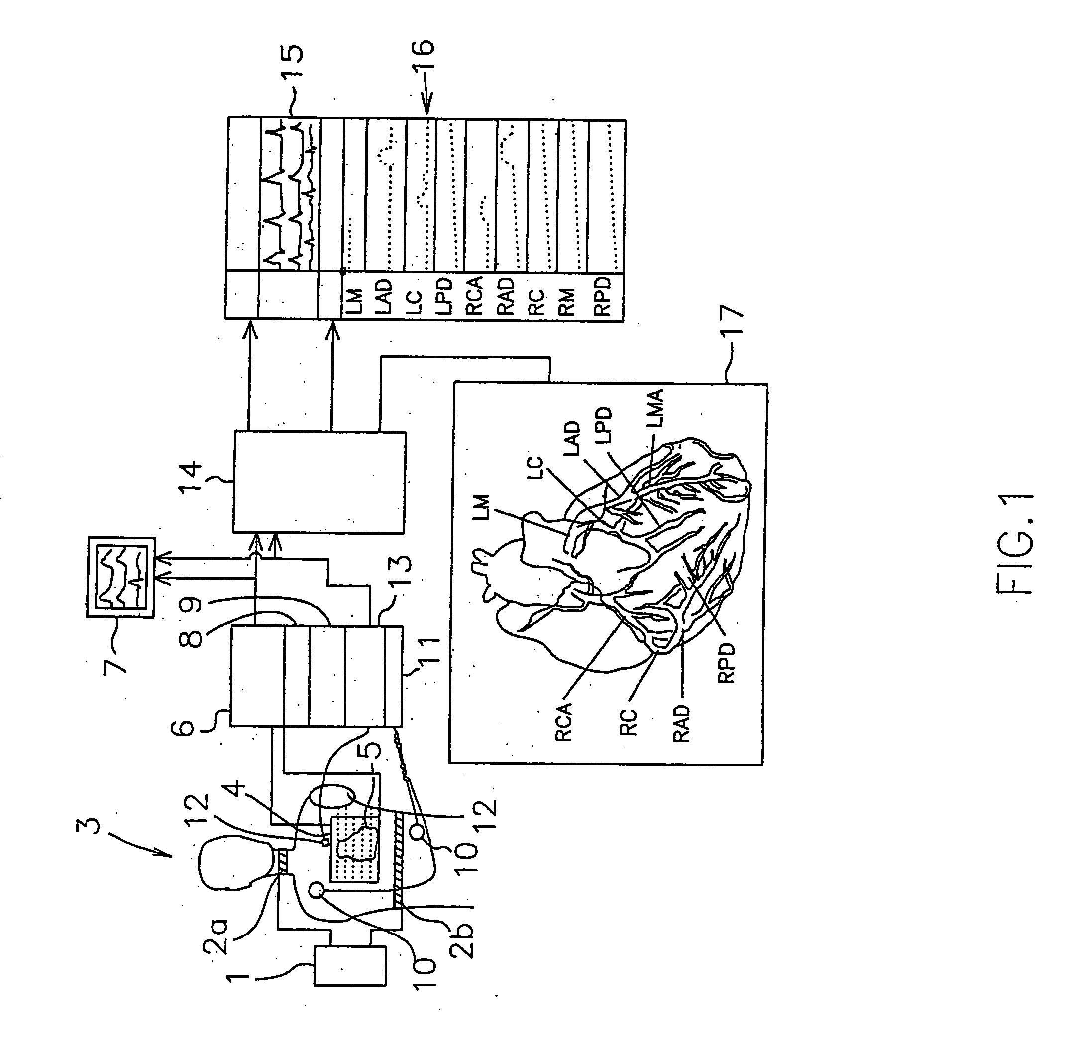
[0055]FIG. 1 shows a diagrammatic overview of the device according to the present invention, as applied to a human body 3. In FIG. 1, reference numeral 1 represents a current source, connected to supply electrodes and, which are applied to the upper part of a human body 3.

[0056] A mesh 4 of measuring electrodes is connected to an impedance measuring means 6, and to scanning means 9. The mesh 4 of measuring electrodes substantially covers the heart 5 of the human body 3. The mesh 4 is a rectangular mesh, with an interelectrode distance of 1 mm, though any other suitable distance is possible.

[0057] The impedance measuring means 6 are connected to a first monitor 7. EKG electrodes 10, which are also applied to the upper part of the human body 3, are connected to EKG measuring means 11. Phonocardiograph 12 is applied to the upper part of the body as well, and are connected to phonocardiogram measuring means 13. A correct position for the phonocardiagraph means 12 is at the 3rd interco...


PUM


Abstract

The present invention provides a method and a device for determining a peak blood flow signal of a blood flow through at least a section of a selected coronary artery of a beating heart of a mammal, in particular a human being, wherein said device comprises a bioimpedance measuring device. The method and device selects part of a bioimpedance signal, and calculates a peak velocity from it. This may e.g. be used to map the peak blood flow velocity along a coronary artery, in order to find possible stenoses in the vessel.

Description

FIELD OF THE INVENTION [0001] The present invention relates to a device and a method for determining a peak blood flow signal of a blood flow through at least a section of at least one selected coronary artery of a beating heart of a mammal, in particular a human being. In particular, the device and method may be used to help determine the location of stenosis in a coronary artery. BACKGROUND OF THE INVENTION [0002] Stenosis is a stricture or narrowed passage in a blood vessel. This may have various causes, but often it is caused by the deposition of fatty substances on the inner wall of the blood vessel. The narrowed passage may hinder the flow of blood and hence the oxygen supply e.g. to a muscle. A very important example of stenosis is the stenosis in a coronary artery, which provides blood to the heart muscle. The treatment of coronary stenosis is a major and very costly part of health care. [0003] Hence, many efforts have been made to develop methods and systems for the detecti...

Claims


Application Information

Patent Timeline
Patent Type & Authority Applications(United States)
IPC IPC(8): A61B5/02A61B5/04A61B5/0402A61B5/053A61B7/04
CPCA61B5/0402A61B5/7239A61B7/04A61B5/0535A61B5/318
Inventor JUDY, WILLIAM V.
Owner IMPEDANCE VASCULAR IMAGING PROD
Why Eureka
Try Eureka