Device for thermally clamping and releasing tools in shrink-fit chucks

a technology of clamping and releasing tools, which is applied in the direction of turning apparatuses, induction heating, induction heating apparatuses, etc., can solve the problems of entail considerable expense, slow indirect cooling achieved in this way, and negative impact on productivity, etc., and achieves rapid cooling, cost reduction, and time saving

Active Publication Date: 2005-09-22
OTTO BILZ WERKZEUGFAB
View PDF3 Cites 5 Cited by
  • Summary
  • Abstract
  • Description
  • Claims
  • Application Information

AI Technical Summary

Benefits of technology

[0003] The object of the present invention is to produce a device of the type mentioned at the beginning, w

Problems solved by technology

The indirect cooling achieved in this way is relatively slow, which has a negative impact on productivity.
It is also necessary

Method used


Image

  • Device for thermally clamping and releasing tools in shrink-fit chucks
  • Device for thermally clamping and releasing tools in shrink-fit chucks
  • Device for thermally clamping and releasing tools in shrink-fit chucks

Examples


Embodiment Construction

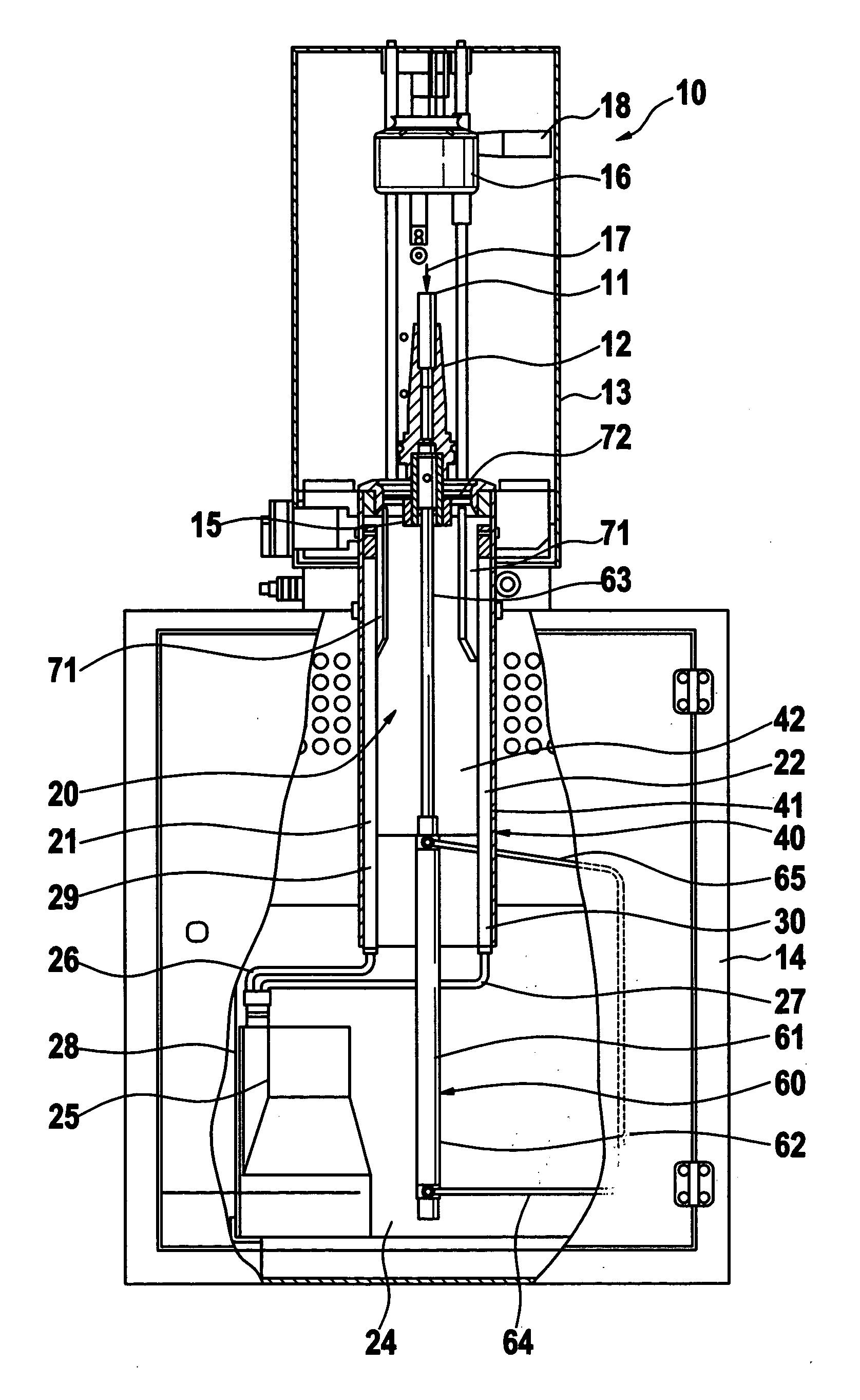
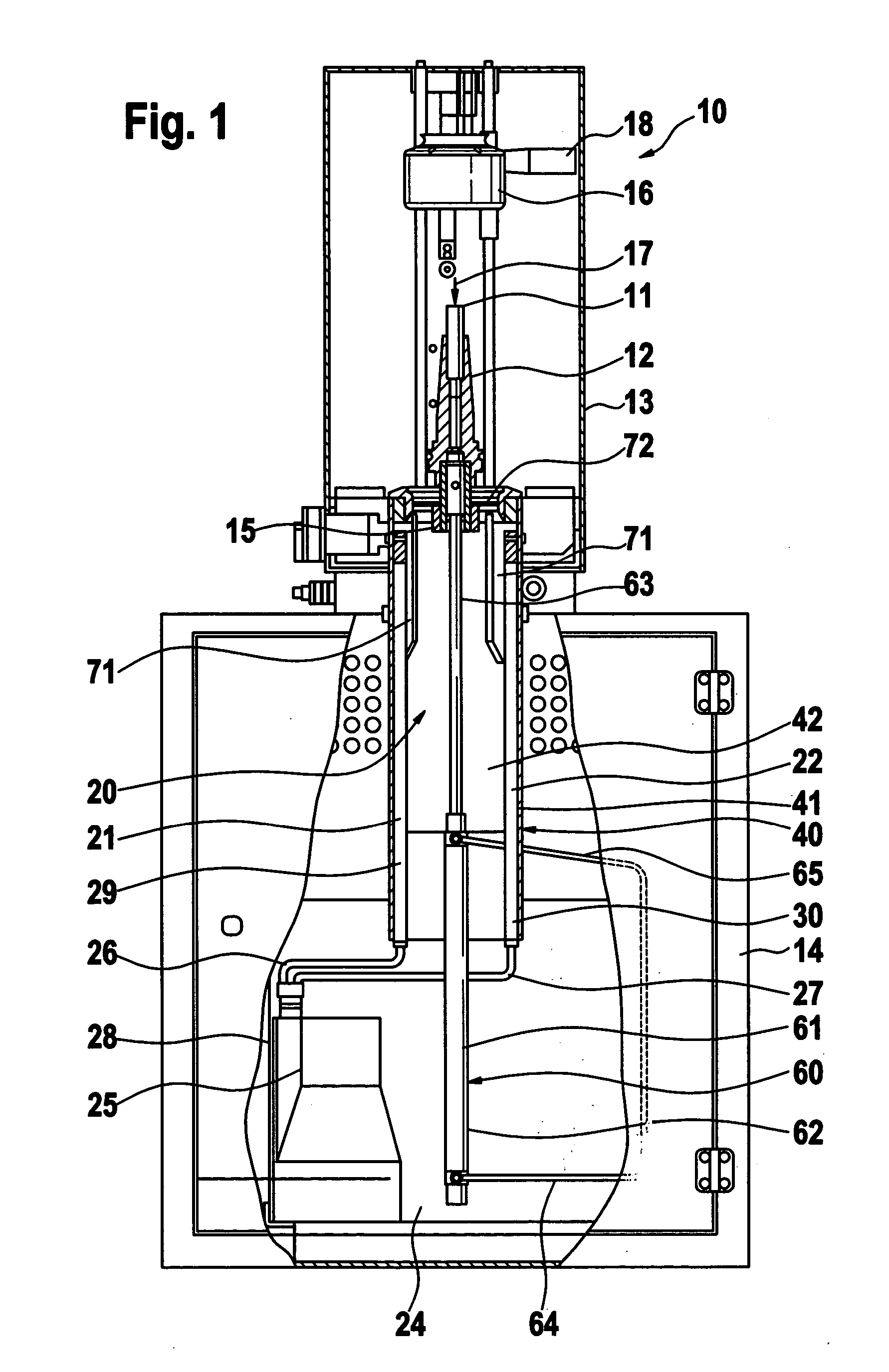
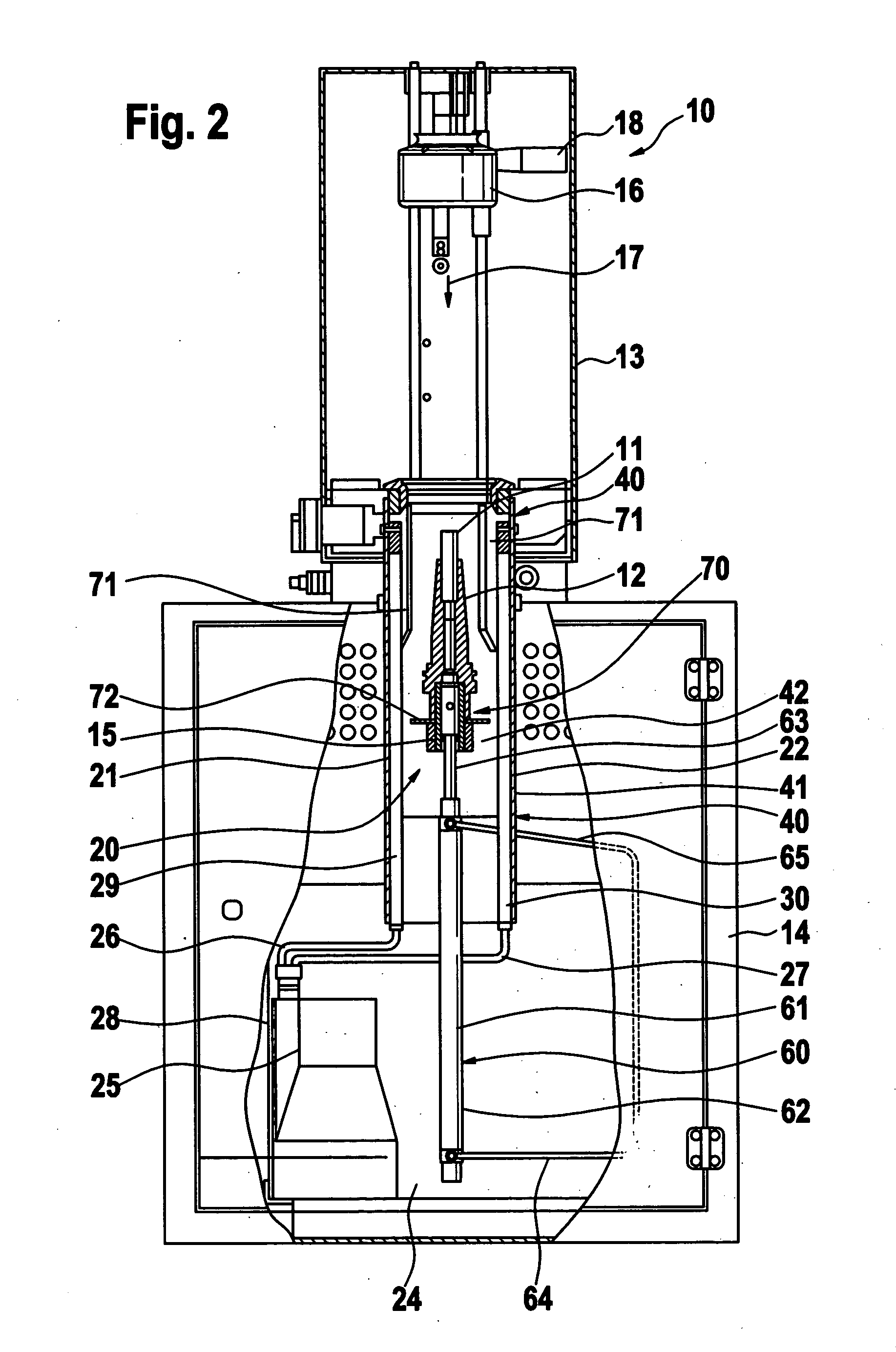
[0013] The drawings show a device 10—which is also referred to as a shrink-fitting unit—in the form of an upright unit, which is used for thermally clamping and releasing tools 11 in shrink-fit chucks 12 and which makes it possible during continuous operation to clamp or release a large number of high-speed tools 11 in rapid succession as often as desired, using the shrink-fitting technique. The device 10 has an upper part 13 and a lower cabinet 14, which contains individual supply units of the. device 10. The device 10 has a socket 15 that can interchangeably accommodate a shrink-fit chuck 12. Another component of the device 10 is a heating unit 16 that can move in the arrow direction 17 toward the socket 15 with the shrink-fit chuck 16 and back away from it in the opposite direction. The heating unit 16 has a protruding handle 18 and inside, an induction coil that is not shown in detail. The handle allows the heating unit to be moved back and forth by hand in the direction of the ...


PUM

PropertyMeasurementUnit
Angleaaaaaaaaaa

Abstract

A device (10) for thermally clamping and releasing tools (11) in shrink-fit chucks (12), having a socket (15) for a shrink-fit chuck (12), a heating unit (16) that can be moved toward and away from the mounted shrink-fit chuck (12), and a cooling unit (20) for cooling the heated shrink-fit chuck (12). The cooling unit (20) has at least one coolant distributor (21, 22) that is capable of moving in relation to the socket (15) with the mountable shrink-fit chuck (12), conveys a preferably fluid coolant, e.g. cooling water, and has outlets (23) for the coolant, which are oriented toward the socket (15) with the mountable shrink-fit chuck (12) and out of which the coolant travels under pressure to act on the outside of the socket (15) with the mountable shrink-fit chuck (12) for cooling purposes (FIG. 1).

Description

BACKGROUND OF THE INVNTION [0001] The invention relates to a device for thermally clamping and releasing tools in shrink-fit chucks. [0002] Devices of this kind are known (DE 10025004 Al), in which the cooling device has a special cooling adapter with an insertable, interchangeable insert that is geometrically adapted to the shape of the shrink-fit chuck used; the cooling adapter contains internal cooling conduits through which a fluid coolant, e.g. cooling water, is circulated for cooling purposes. In order to cool the shrink-fit chuck, the cooling adapter with the interchangeable insert adapted to the chuck geometry is slid onto the shrink-fit chuck. The indirect cooling achieved in this way is relatively slow, which has a negative impact on productivity. It is also necessary to store and use a specifically adapted cooling adapter for each shrink-fit chuck geometry, which entails considerable expense. SUMMARY OF THE INVENTION [0003] The object of the present invention is to produc...

Claims


Application Information

Patent Timeline
IPC IPC(8): B23P11/02H05B6/14H05B6/42
CPCB23B31/1179B23P11/027H05B6/14Y10T29/53439Y10T279/35Y10T279/17957H05B6/42
Inventor STEUDTE, RUEDIGER
Owner OTTO BILZ WERKZEUGFAB
Why Eureka
Try Eureka