Non-contact fluid particle cleaner and method

a technology of non-contact fluid and particle cleaner, which is applied in the direction of cleaning equipment, cleaning using liquids, transportation and packaging, etc., can solve the problems of adding processing costs, product handling steps, and sometimes transferring chemicals, and achieves the effect of increasing the residence tim

Inactive Publication Date: 2005-09-22
IBM CORP
View PDF9 Cites 10 Cited by
  • Summary
  • Abstract
  • Description
  • Claims
  • Application Information

AI Technical Summary

Benefits of technology

[0008] The invention includes a non-contact fluid particle cleaner and method that provides a partition to a side of a fluid nozzle to form: a central cavity configured to define the fluid departing the surface into a central cavity vortex; and a side cavity adjacent the central cavity to define fluid escaping from the central cavity into a side vortex. The vortices interact in a counter-rotating and stationary fashion. The strong and smaller central vortex creates an upward air velocity field that forces any airborne particle to move away from the surface. The side vortex is designed to: connect the central vortex velocity field to a vacuum flow and allow airborne particles to remain suspended until they reach the vacuum flow; and create a decelerating field for high speed particles traveling parallel (horizontally) to the surface to increase the residence time in the central vortex.

Problems solved by technology

Unfortunately, one or just a few of such escaping particles can have a direct impact on yield and screening process performance in the semiconductor industry.
However, this approach is not always applicable to all situations and adds processing cost, product handling steps, and sometimes transfers chemicals to the surface being cleaned.

Method used


Image

  • Non-contact fluid particle cleaner and method
  • Non-contact fluid particle cleaner and method
  • Non-contact fluid particle cleaner and method

Examples


Embodiment Construction

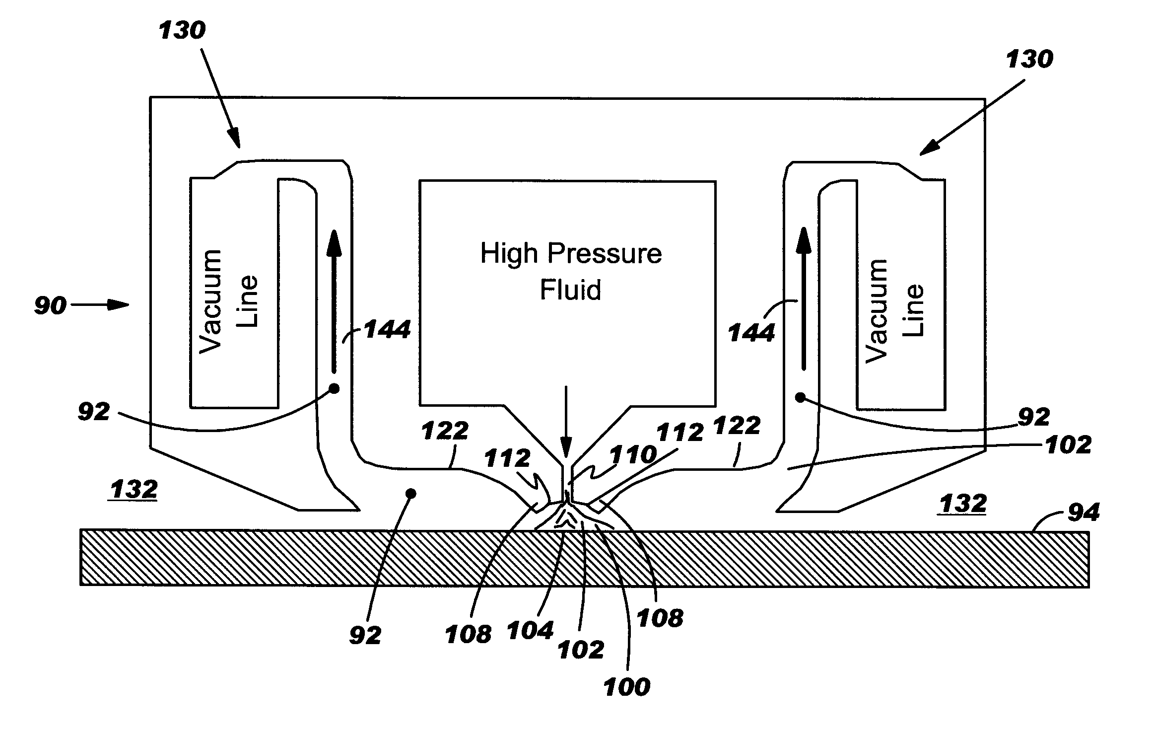
[0020] With reference to the accompanying drawings, FIG. 3 illustrates a cleaner 90 for non-contacting removal of particles 92 from a surface 94 by propelling a fluid 100 (via a fluid jet 102) onto a jet contact area 104 of surface 94 according to the invention. Cleaner 90 includes at least one partition 108 adjacent a fluid nozzle 110 that when cleaner 90 is in close proximity to surface 94, defines cavities where fluid 100 can circulate in a predetermined flow pattern that is efficient to remove particles from surface 94. Cleaner 90 does not contact surface 94, and may be, for example, 10-40 mils away from surface 94. For purposes of clarity, the fluid upon with which the invention is described is air. It should be recognized, however, that the teachings of the invention are modifiable to apply to any fluid including, for example, gases and / or liquids. In one embodiment, cleaner 90 is constructed such that it extends in a planar fashion, i.e., into and out of the page, such that f...


PUM


Abstract

A fluid particle cleaner and method are disclosed. The invention provides a partition to a side of a fluid nozzle to form: a central cavity configured to define the fluid departing the surface into a central cavity vortex; and a side cavity adjacent the central cavity to define fluid escaping from the central cavity into a side vortex. The vortices interact in a counter-rotating and stationary fashion. The strong and smaller central vortex creates an upward air velocity field that forces any airborne particle to move away from the surface. The side vortex is designed to: connect the central vortex velocity field to the vacuum flow and allow airborne particles to remain suspended until they reach the vacuum flow; and create a decelerating field for high speed particles traveling parallel (horizontally) to the surface to increase the residence time in the central vortex with positive vertical velocity.

Description

BACKGROUND OF INVENTION [0001] 1. Technical Field [0002] The present invention relates generally to fluid jet particle cleaners. More particularly, the present invention relates to a non-contact fluid jet particle cleaner and method that shape fluid vortices to more efficiently remove particles. [0003] 2. Related Art [0004] Fluid jet particle cleaners are commonly used to remove minute particles from products in a wide variety of industries. One illustrative industry in which these cleaners find application is the semiconductor industry. In this industry, yields and mask life in a manufacturing line are very sensitive to the presence of small particles that are less than 5 mils in diameter on the product surface. Fluid jet particle cleaners provide a low cost solution to clean the surface of a product. [0005]FIG. 1 illustrates a conventional fluid jet particle cleaner 10 that propels a fluid 12 such as air onto a surface 14 of a product 16 to release particles therefrom, and then va...

Claims


Application Information

Patent Timeline
Patent Type & Authority Applications(United States)
IPC IPC(8): B08B3/02B08B5/02B08B15/04F17D3/00H01L21/00
CPCB08B3/02B08B5/02B08B15/04Y10S134/902H01L21/67028H01L21/67051B08B2203/0229Y10T137/2087Y10T137/2098
Inventor BEZAMA, RASCHID J.MEDAHUNSI, NIKE O.
Owner IBM CORP
Why Eureka
Try Eureka