

DC-DC converter for boosting input voltage at variable frequency
a converter and variable frequency technology, applied in the direction of dc-dc conversion, power conversion systems, instruments, etc., can solve the problem of increasing the energy of switching noise in the switching frequency, and achieve the effect of reducing switching noise and diffusing nois
- Summary
- Abstract
- Description
- Claims
- Application Information
AI Technical Summary
Benefits of technology
Problems solved by technology
Method used
Image

Examples
first embodiment
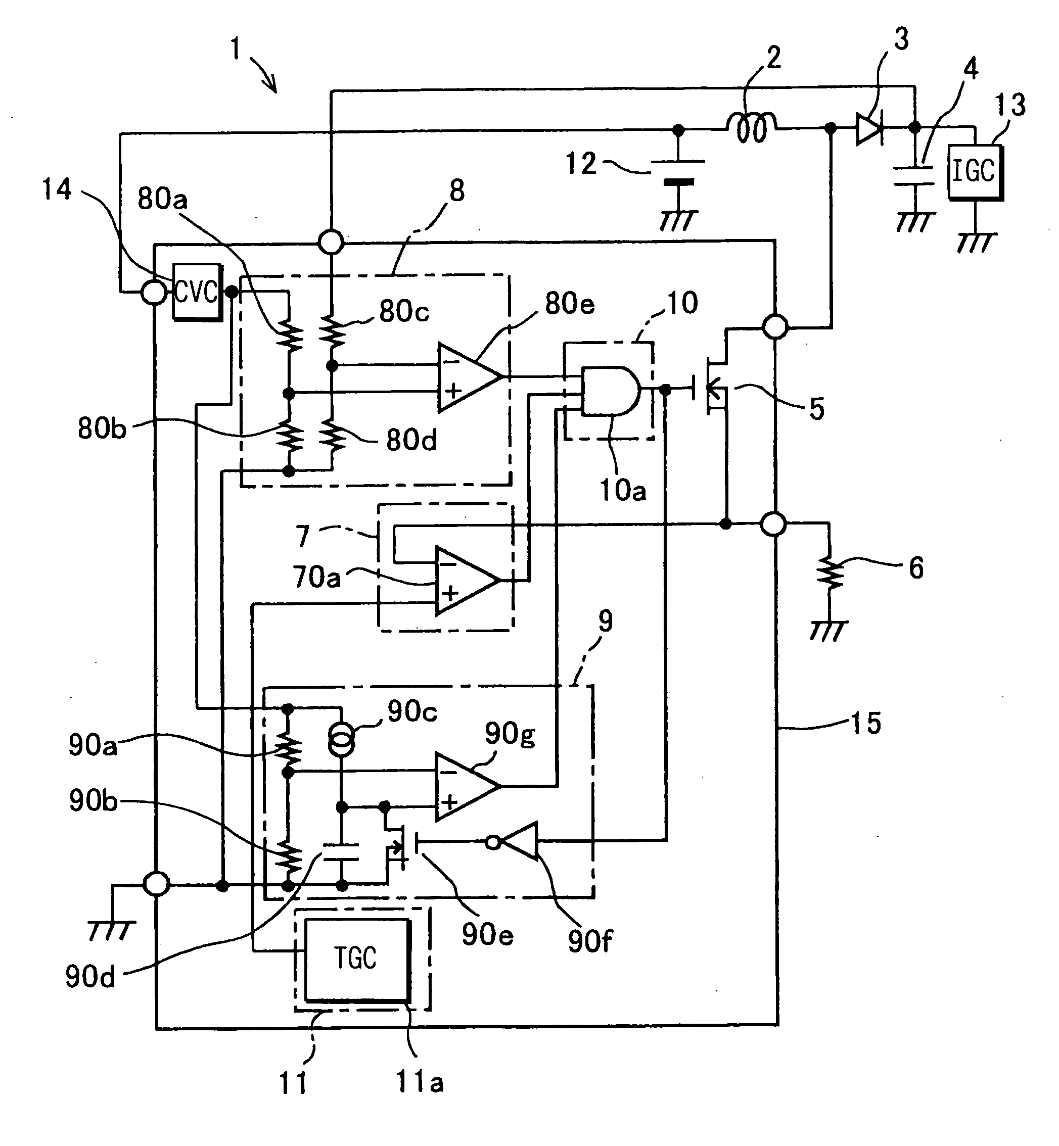
[0020] Referring to FIG. 1, a DC-DC converter 1 includes: an inductor (coil) 2; a diode 3; a capacitor 4; a field effect transistor (FET: switching element) 5; a resistor 6; a first ON signal generating circuit 7; a second ON signal generating circuit 8; an OFF signal generating circuit 9; a transistor driving signal generating circuit (switching element driving signal generating circuit) 10; and a switching frequency varying circuit (FVC) 11.
[0021] The inductor 2 is an element that stores and discharges magnetic energy, and induces voltage. One end of the inductor 2 is connected to the positive pole terminal of a battery 12, and the negative pole terminal of the battery 12 is grounded to a vehicle chassis. The other end of the inductor 2 is connected to one end of the capacitor 4 and one end of an ignition circuit (IGC) 13 of the airbag device through the diode 3. The other end of the capacitor 4 and the other end of the ignition circuit 13 are grounded to the chassis.
[0022] The ...
second embodiment
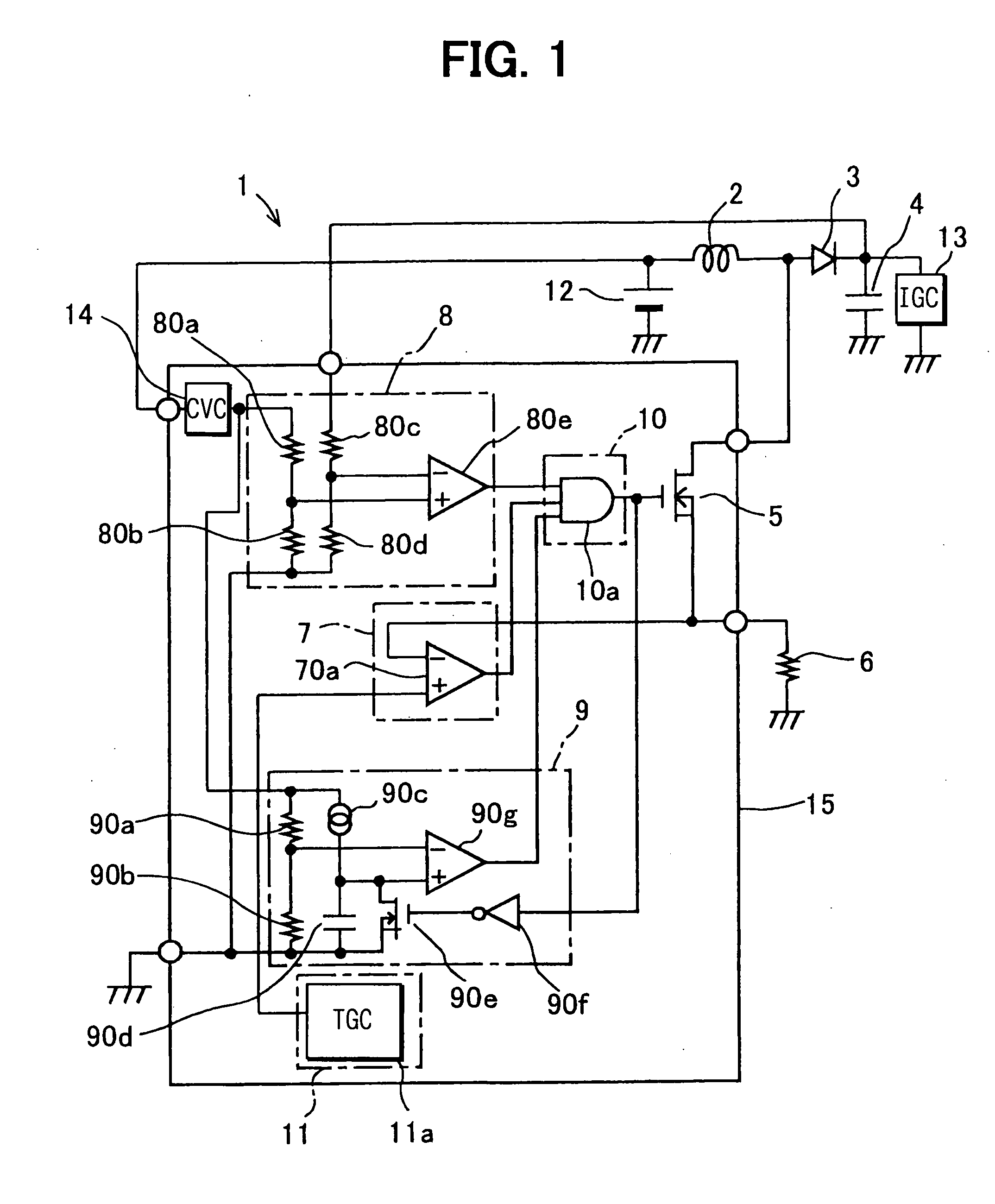
[0048] The second embodiment shown in FIG. 2 is different from the first embodiment in that the switching frequency varying circuit 11 includes a counter circuit (CNTR) 110 and a reference power circuit 111. The counter circuit 110 is a three-bit binary counter that counts switching operations of the field effect transistor 5.
[0049] The reference power circuit 111 successively switches and outputs a plurality of voltages of different magnitudes according to the result of counting by the counter circuit 110. It includes resistors 111a to 111e and field effect transistors 111f to 111h.
[0050] One end of the resistor 111a is connected to the output terminal of the constant voltage circuit 14 that generates the constant voltage from voltage inputted through the circuit power terminal. Its other end is connected to one ends of the resistors 111b to 111e. The other end of the resistor 111b is grounded to the chassis through the ground terminal. The other end of the resistor 111c is conne...
third embodiment
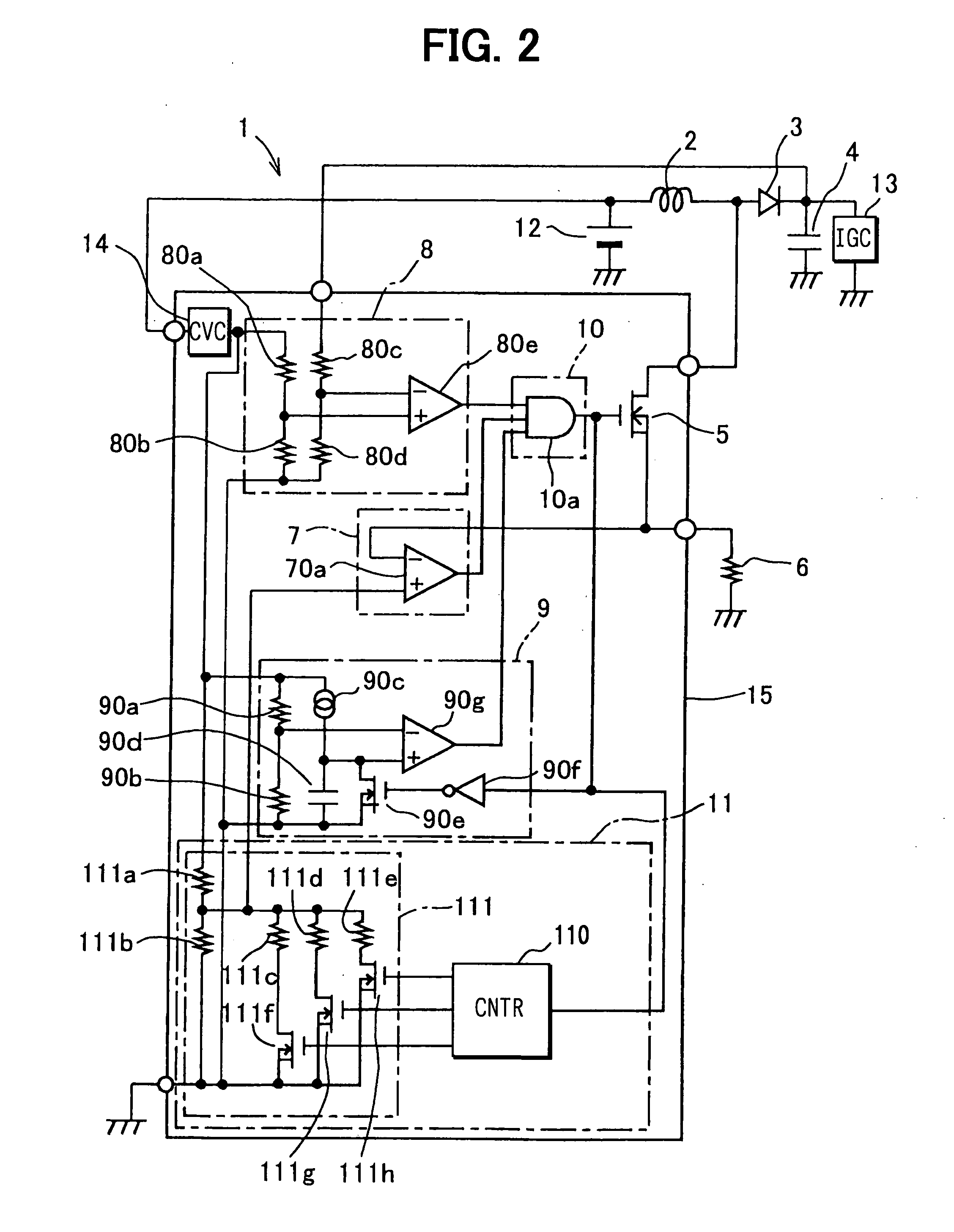
[0057] The third embodiment shown in FIG. 3 is different from the first and second embodiments in respect of the first ON signal generating circuit 7, the OFF signal generating circuit 9 and the switching frequency varying circuit 11.
[0058] The first ON signal generating circuit 7 includes resistors 70b and 70c in addition to the comparator 70a. The resistors 70b and 70c are connected in series. One end of the resistors 70b and 70c connected in series is connected to the output terminal of the constant voltage circuit 14 that generates the constant voltage from voltage inputted through the circuit power terminal. The other end is grounded to the chassis through the ground terminal. The resistors 80a and 80b, which determine the specified voltage threshold value, are set to an optimum value so that a coil current required is obtained.
[0059] The inverting input terminal of the comparator 70a is connected to the source of the field effect transistor 5 and the resistor 6 through the c...
PUM
 Abstract
Description
Claims
Application Information