Automatic range finder for electric current testing

Active Publication Date: 2005-09-22
QUALITITAU INC
View PDF9 Cites 18 Cited by
  • Summary
  • Abstract
  • Description
  • Claims
  • Application Information

AI Technical Summary

Benefits of technology

[0008] In carrying out the invention, in one embodiment a range finder comprising a pair of diode-connected bipolar transistors are connected in parallel and in opposing directions for use with a current source or a current sink. By

Problems solved by technology

However, the transition from the last point of one sequence to the first point of the next sequence often requires many such changes until the

Method used


Image

  • Automatic range finder for electric current testing
  • Automatic range finder for electric current testing
  • Automatic range finder for electric current testing

Examples


Embodiment Construction

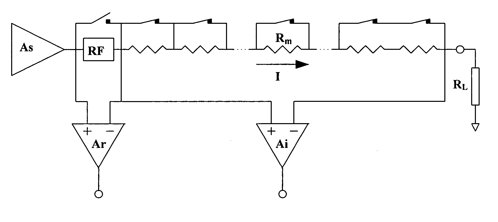
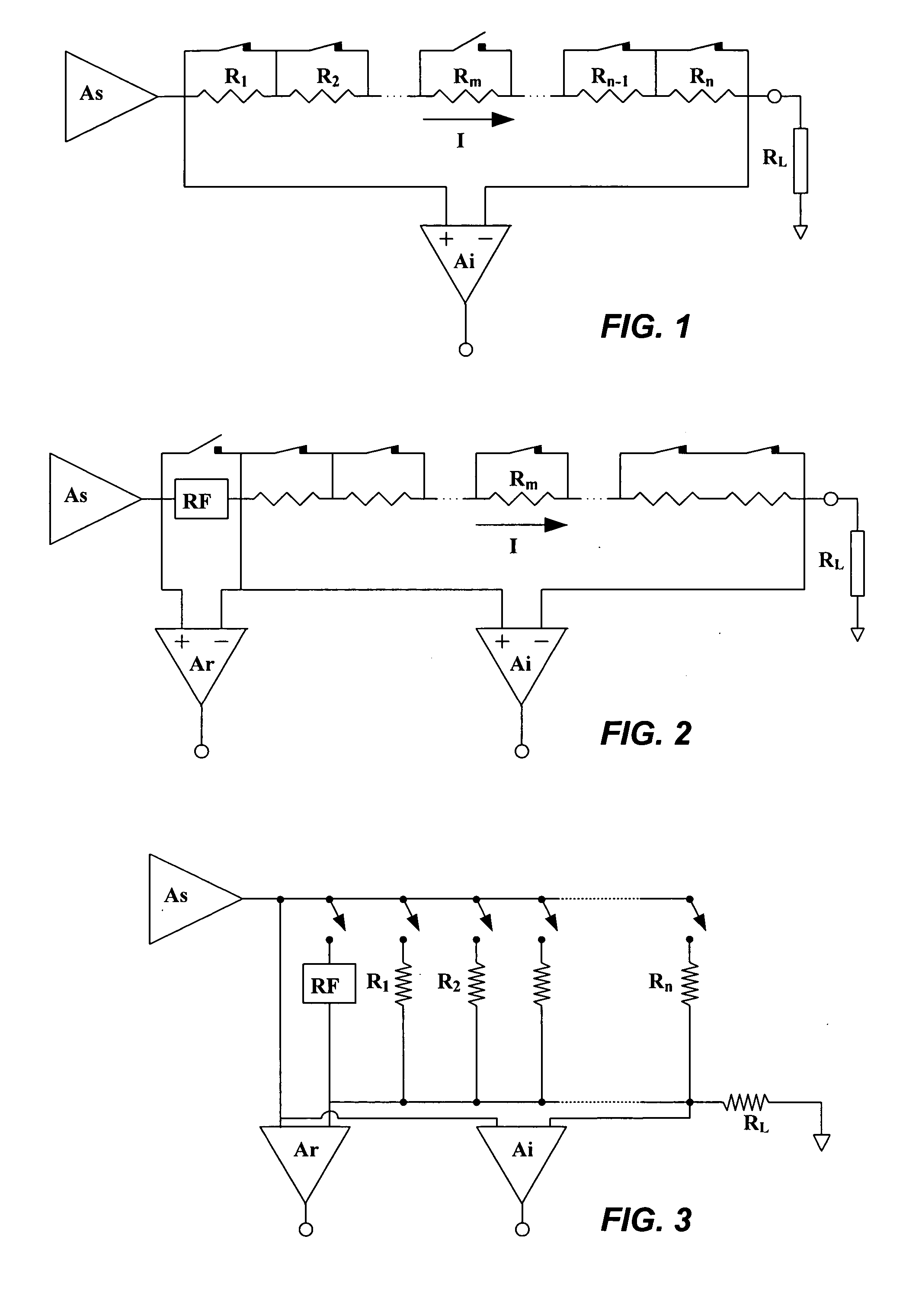
[0016] Most high accuracy current measuring systems (SPTs in particular) utilize sensing element(s), connected in series with the load. In general, the measured magnitude is the resulting voltage across the sensing element, while its a-priori known current vs. voltage relation is used to determine the current. Typically, high precision resistors are the preferred sensing elements, since: (i) they follow a linear current vs voltage relation (Ohm's law) almost perfectly; (ii) they are hardly influenced by temperature; (iii) they are easily available over a wide range of values, as required for the different sub-ranges; and (iv) overall, their performance to price ratio is excellent. However, since high voltage drops across such resistors limit the maximum voltage available to the load on one hand, while very low voltage drops compromise measurement accuracy on the other hand, most current sub-ranges cover only one or two orders of magnitude. This translates to many current sub-ranges,...


PUM


Abstract

In an electrical for testing electrical current using a plurality of precision resistors connected in parallel or in series, a range finder for receiving the current to be measured with the voltage drop across the range finder being indicative of a current sub-range for measurement. In a preferred embodiment, a range finder comprises a first bipolar transistor and a second bipolar transistor connected in parallel and in opposite polarity with the emitter and base of each transistor connected together whereby each transistor functions as an emitter-base diode.

Description

CROSS-REFERENCE TO RELATED APPLICATIONS [0001] This application claims priority from copending provisional application Ser. No. 60 / 553,859, filed Mar. 16, 2004, which is incorporated herein by reference for all purposes.BACKGROUND OF THE INVENTION [0002] This invention relates generally to measuring electrical current such as in semiconductor device testers, and more particularly the invention relates to the use of a current range finder to expedite the selection of current sub-ranges for testing. [0003] Measuring electric current (hereinafter “current”) accurately is a key requirement for all parametric testers, in particular those used for semiconductor devices characterization (“SPT” for “Semiconductor Parametric Tester”). The wide range of semiconductor devices and applications implies measured current levels as low as 1e-12 A (pA) and as high as 1 A, namely many orders of magnitude or decades of current. This leads to optimization techniques, in which the entire range of curren...

Claims


Application Information

Patent Timeline
IPC IPC(8): G01R1/00G01R19/00G01R19/165G01R31/26
CPCG01R19/0092G01R19/16561G01R15/09G01R31/2608G01R31/2621G01R19/1659
Inventor KRIEGER, GEDALIAHOOCUEVAS, PETER P.BORTHWICK, JAMES
Owner QUALITITAU INC
Why Eureka
Try Eureka