
Method for cell modification in mobile communication system

a mobile communication system and cell technology, applied in the field of cell conversion method in radio resource management, can solve the problems of pilot signal strength hysteresis, burden of scheduling operation for all nodes b, and require extremely tight timing

Inactive Publication Date: 2005-09-22
PANASONIC CORP
View PDF6 Cites 168 Cited by
  • Summary
  • Abstract
  • Description
  • Claims
  • Application Information

AI Technical Summary

Benefits of technology

"The invention aims to provide a method and system for changing cells in a cellular system without causing data loss or delay during the process. The technical effect of the invention is to improve the reliability and efficiency of cellular networks by reducing the impact of cell change procedures on data transmission."

Problems solved by technology

Hence, addition and removal events form a hysteresis with respect to pilot signal strengths.
Applying soft handover would cause the burden of scheduling operation for all Node B's within the active set.
Even if this problem is solved, it would require extremely tight timing to provide the scheduling decision to all members of the active set.
Therefore, soft handover is not supported for HS-PDSCH.
The margin also contributes to handover delay.
It should be noted that executing inter-Node B serving HS-DSCH cell change procedure also implies executing a “serving HS-DSCH Node B relocation procedure” and this is where the problems of HARQ context relocation arise.
However, several problems may occur during the conventional inter-Node B serving cell change procedure, as will be described in more detail as follows.
These problems may be summarized to relate to a packet loss and delay due to the cell change procedure, and to frequent cell changes due to the decision delay.
First, the packet loss problem due to the cell change procedure is discussed.
This would involve a significant transfer delay and that is why current solutions are limited to flushing the reordering buffer at the UE side and transferring all successfully received packets to a higher layer when the Node B relocation procedure has to be performed.
Further, this data loss may also result in an additional delay.
Apart from handover delays which are specific for all procedures and which may result from measurement and synchronization delays as shown above, there is an additional delay introduced by data loss.
This delay is incurred due to compensation of lost packets.
These will cause an additional delay mainly due to retransmitting these packets over interfaces of transport network.
This increased delay can trigger a spurious timeout of a reliable transport protocol (TCP) used for end-to-end (inter-end-terminal) transmissions and it may slow down the data rate of packets that are input to UTRAN due to congestion control mechanisms.
However, due to the invoked TCP congestion control, the number of packets that are available for scheduling remains decreased and radio resources are not utilized efficiently.
Even more severe problems can occur in a network that has the RLC protocol configured in the unacknowledged mode, or in a conceptual network that has retransmission protocol entities just in the Node B and UEs.
In this case all packets lost from the HARQ context would have to be retransmitted end-to-end thus causing even higher delay and inefficient usage of radio resources.
Further problems may arise with frequent cell changes due to the decision delay.
However, switching the HSDPA service to the new member cell simultaneously with the radio link addition does not necessarily have to be an optimal decision.
The problem may arise in particular when the serving cell change and the active set update procedures are not synchronized.
If the decision on triggering the cell change procedure has been made with a significant delay, the channel conditions may change back by the time the procedure is complete.
This would result in a continuous ping-pong behavior between cells during which it is not possible to schedule the user.

Method used


Image

  • Method for cell modification in mobile communication system
  • Method for cell modification in mobile communication system
  • Method for cell modification in mobile communication system

Examples


Embodiment Construction

[0070] Embodiments of the present invention will be described below with reference to the accompanying drawings.

[0071] Before discussing in more detail the protocol context preservation according the invention, an HSDPA architecture will first be described with reference to FIGS. 7 to 9, in which the invention may be used.

[0072] First, with reference to FIG. 7, the UE HSDPA architecture is explained. It can be noted that each HARQ process 700, 705, 710 is assigned a certain amount of soft buffer memory for combining the bits of the packets from outstanding retransmissions. Once a packet is received successfully, it is forwarded to the reordering buffer 720, 730, 740 providing the in-sequence delivery to the RLC sublayer. According to this architecture, the reordering queue may be tied to a specific priority.

[0073] It should be noted that the available soft buffer size may depend on UE radio access capability parameters such as those described in 3GPP TSG RAN, “Physical Layer Aspe...


PUM


Abstract

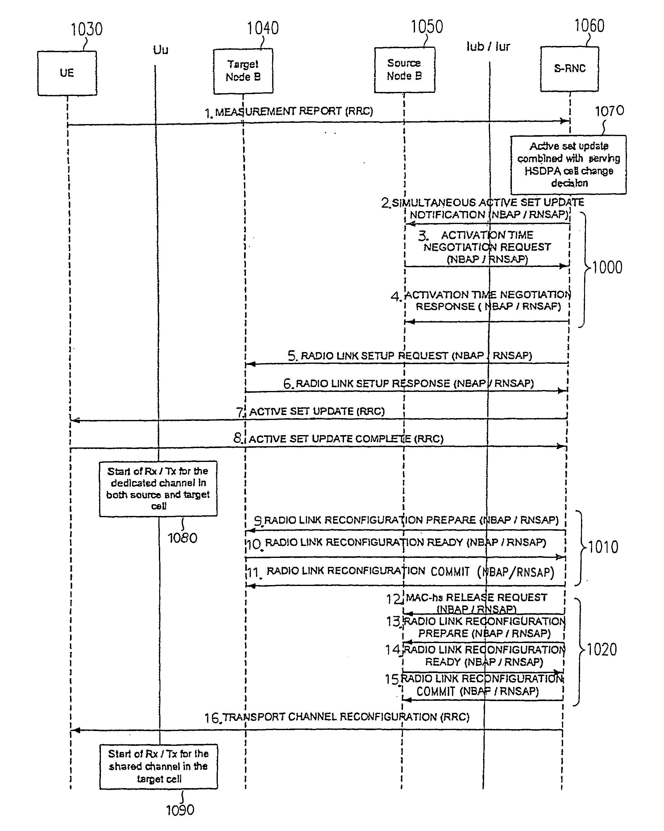
S-RNC 1060 determines the need for the combined radio link addition and serving HS-DSCH cell change based on received measurement reports, and makes a decision for starting an active set update and cell change procedure (process 1070). After that, it notifies immediately to source base station (Source Node B) 1050 that the decision on active set update was done (signaling 2). Source Node B 1050 transmits an ACTIVATION TIME NEGOTIATION REQUEST message (signaling 3) to S-RNC 1060. S-RNC 1060 transmits an ACTIVATION TIME NEGOTIATION RESPONSE message (signaling 4) to Source Node B 1050. Source Node B 1050 knows activation time through this, and ceases capacity assignment for transmitting data to UE 1030, while transmitting buffered packets to UE 1030 with a priority made higher than those of other UEs.

Description

FIELD OF THE INVENTION [0001] The present invention relates to a cell conversion method in radio resource management applicable to mobile communication systems and particularly to cellular systems. BACKGROUND ART [0002] A common technique for error detection of non-real time services in communication systems is Automatic Repeat reQuest (ARQ) schemes that may be combined with Forward Error Correction (FEC). In ARQ, if an error is detected in PDU (Protocol Data Unit) by Cyclic Redundancy Check (CRC), the receiver requests the transmitter to send additional bits. In mobile communication, SAW (Stop-And-Wait) scheme and SR (Selective-Repeat) scheme are most often used among existing ARQ schemes. SAW scheme is a scheme in which a transmitter sends a PDU, and transmits the next PDU after confirming that there has been no repeat request from a receiver for a certain time period. SR scheme is a scheme in which a sequence number is assigned to a PDU, and retransmission is performed only for P...

Claims


Application Information

Patent Timeline
Patent Type & Authority Applications(United States)
IPC IPC(8): H04L12/56H04W28/10H04W28/26H04W36/00H04W36/12H04W72/04H04W84/04
CPCH04W28/10H04W28/26H04W84/04H04W36/12H04W72/10H04W36/00H04W72/56H04W36/04
Inventor PETROVIC, DRAGANSEIDEL, EIKO
Owner PANASONIC CORP
Learn More