Eureka AIR delivers breakthrough ideas for toughest innovation challenges, trusted by R&D personnel around the world.

Wavelength stabilized diode-laser array

Inactive Publication Date: 2005-09-22
COHERENT INC
View PDF15 Cites 49 Cited by
  • Summary
  • Abstract
  • Description
  • Claims
  • Application Information

AI Technical Summary

Problems solved by technology

If a fiber-laser is required to provide a high power output, for example, greater than about 3.0 Watts (W), a single diode-laser emitter may not be capable of providing sufficient pump light power.
This relatively high temperature sensitivity, combined with the range of emitting wavelengths, makes a multimode diode-laser bar unsuitable for pumping a fiber-laser lasers wherein pump light must be absorbed in a narrow band of wavelengths.

Method used


Image

  • Wavelength stabilized diode-laser array
  • Wavelength stabilized diode-laser array
  • Wavelength stabilized diode-laser array

Examples


Embodiment Construction

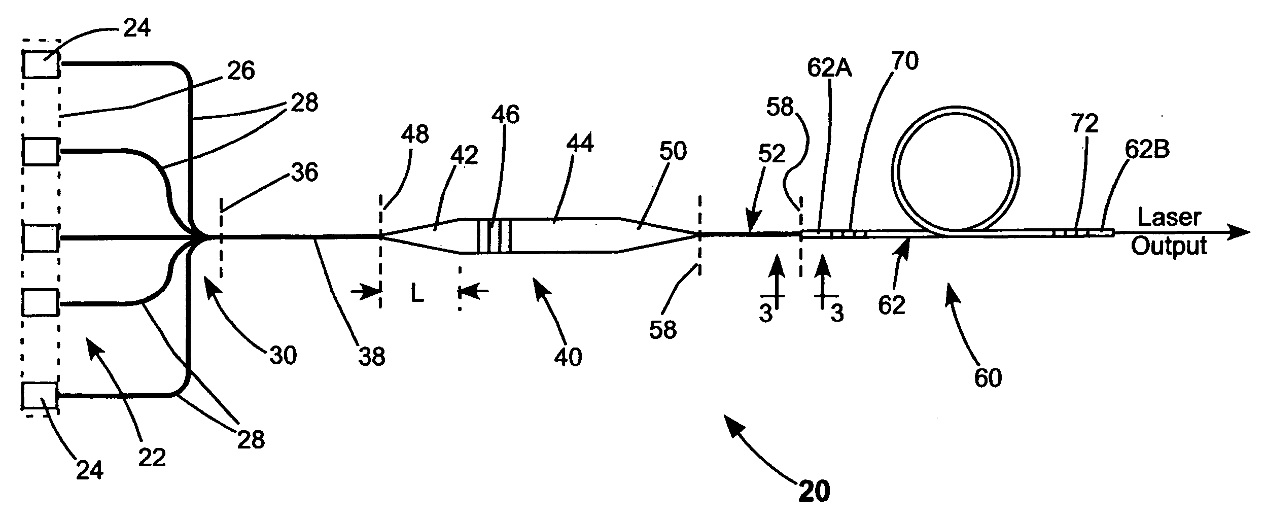
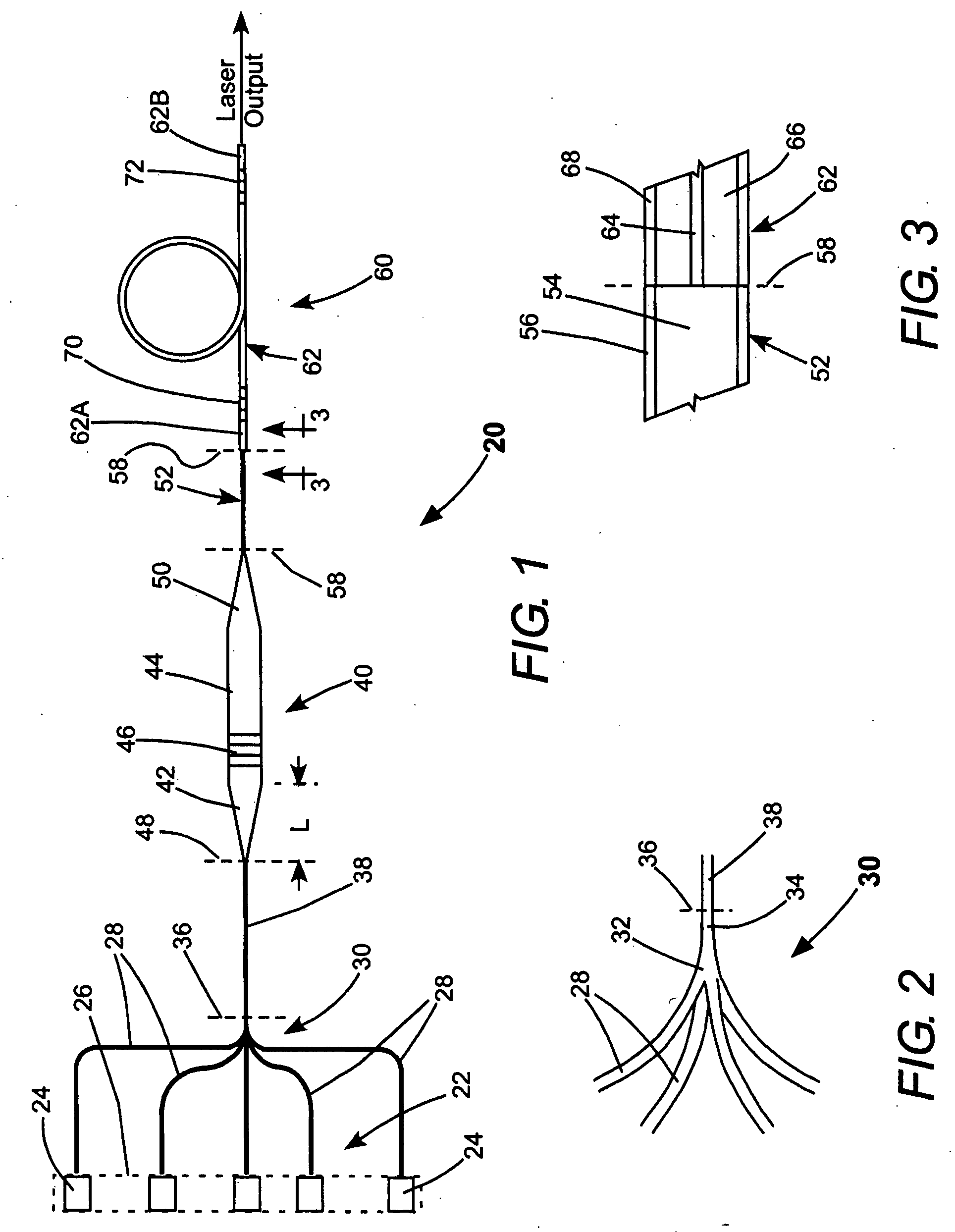
[0018] Referring now to the drawings, wherein like features are designated by like reference numerals, FIG. 1, FIG. 2, and FIG. 3 schematically illustrate one embodiment of a cladding pumped fiber-laser 20, optically pumped by a diode-laser array 22. Diode-laser array 22 is wavelength stabilized by a preferred embodiment of the wavelength stabilizing method of the present invention. Diode-laser array 22 includes a plurality of individual diode-lasers or emitters 24. These may be emitters in a diode-laser bar, indicated in phantom in FIG. 1 by dotted rectangle 26, or could be individual diode-lasers on separate substrates. A multimode optical fiber 28 is provided for each emitter 24. Light (not shown) emitted from each of the emitters 24 is coupled into a corresponding multimode fiber 28 as illustrated in FIG. 1. As methods for coupling light from a diode-laser array into a corresponding array of optical fibers are well known in the art to which the present invention pertains, a deta...


PUM


Abstract

A fiber laser including doped-core fiber having inner and outer cladding is optically pumped by plurality of diode-lasers. Light emitted by the diode-lasers is coupled into a single multimode optical fiber. Light from the multimode optical fiber is directed to a wavelength selective reflecting device that is partially reflective in a narrow reflection band about a peak reflection wavelength. A portion of the light having the peak reflection wavelength is reflected from the wavelength selective reflecting device back along the multimode optical fiber and back into the plurality of diode-lasers. This locks the emitting wavelength of the light emitted from each of the diode-lasers to the peak reflection wavelength. Light at the emitting wavelength that is not reflected from the wavelength selective reflective device is coupled into the inner cladding of the doped-core fiber for optically pumping the fiber laser.

Description

TECHNICAL FIELD OF THE INVENTION [0001] The present invention relates generally to cladding-pumped fiber-lasers. The invention relates in particular to a fiber-laser, cladding pumped by multiple diode-laser emitters that are wavelength locked by a common wavelength-locking device. DISCUSSION OF BACKGROUND ART [0002] Fiber-lasers are commonly pumped by light from a diode-laser. One preferred fiber-laser type that is suitable for diode-laser pumping is referred to by practitioners of the art as a double-clad fiber-laser or a cladding pumped fiber-laser. The double clad fiber-laser has a doped core that provides optical gain when energized by the pump light from the diode-laser. Surrounding the doped core is an inner cladding and surrounding the inner cladding is an outer cladding. The diode-laser light (pump light) is directed into the inner cladding of the fiber-laser and propagates through the inner cladding while being progressively absorbed in the doped core, thereby energizing (p...

Claims


Application Information

Patent Timeline
IPC IPC(8): H01S3/094H01S3/30H01S5/12H01S5/14H01S5/40
CPCH01S3/094003H01S3/094007H01S5/4062H01S5/146H01S5/12
Inventor STARODOUMOV, ANDREIREED, MURRAY KEITH
Owner COHERENT INC
Why Eureka
Eureka Blog
Learn More