Transmit/receive filter and method for manufacturing same

a filter and transmit/receive technology, applied in waveguide devices, digital transmission, electrical devices, etc., can solve the problems of inability to efficiently miniaturize elements, inability to use high transmit or receive frequencies, and high cost of circuits, etc., to achieve small metallization loss, small implementation complexity, and size and cost advantages

Inactive Publication Date: 2005-09-22
INFINEON TECH AG
View PDF10 Cites 20 Cited by
  • Summary
  • Abstract
  • Description
  • Claims
  • Application Information

AI Technical Summary

Benefits of technology

[0014] It is possible by means of the inventive concept to replace the multi-layered carrier material entailing the problems mentioned above by a single-layered substrate or by a simple MMIC package (MMIC=monolithic microwave integrated circuit). A passive chip comprising the discrete phase shifter can, for example, be arranged on the single-layered substrate. Size and cost advantages result from this. Furthermore, the high-frequency characteristics of the transmit and / or receive filter assemblies can inventively be influenced and improved selectively by associating ground islands. Small metallization losses and a small implementation complexity additionally result when manufacturing the inventive transmit / receive filter. Due to the reduced size, the inventive transmit / receive filters can be integrated into complex systems on the basis of a multi-chip mounting, the result being further cost advantages compared to other structures. In addition, the inventive transmit / receive filter comprises good thermal characteristics since the chips having the three elements of a transmit filter assembly, a receive filter assembly and a discrete phase shifter can, for example, be arranged on separate substrate portions spaced apart from one another. Since the inventive transmit / receive filter can be housed easily, the manufacturing and implementation complexity can additionally be reduced.

Problems solved by technology

It is a disadvantage of this approach that circulators are expensive and can only be used with higher transmit or receive frequencies.
It is a disadvantage of the approach described above that strip lines formed as λ / 4 line transformers are used for decoupling the receive filter and the transmit filter.
In the frequency range mentioned above, such strip-line transformers, however, have considerable lengths up to 20 mm and more so that an efficient element miniaturization is no longer possible.

Method used


Image

  • Transmit/receive filter and method for manufacturing same
  • Transmit/receive filter and method for manufacturing same
  • Transmit/receive filter and method for manufacturing same

Examples


Embodiment Construction

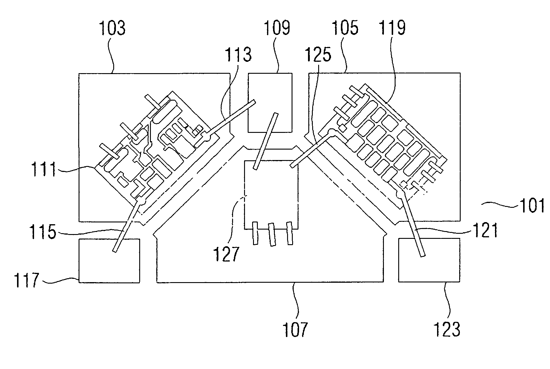
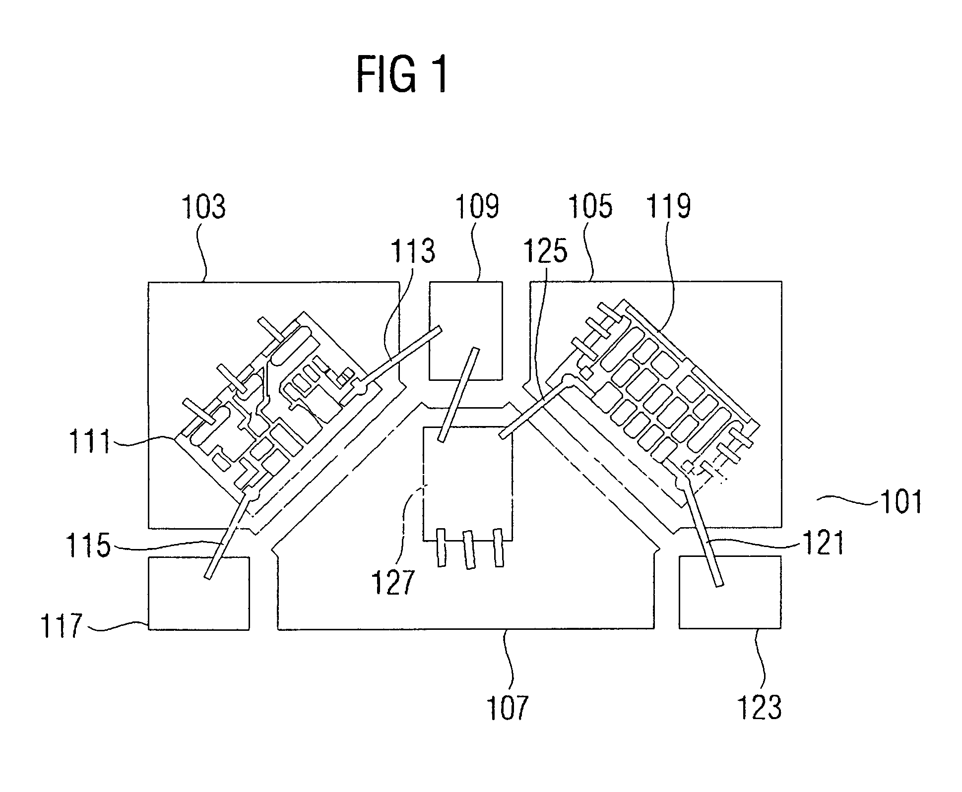
[0025]FIG. 1 shows a transmit / receive filter according to a first embodiment of the present invention. The transmit / receive filter includes a substrate 101 having a first substrate portion 103, a second substrate portion 105 and a third substrate portion 107. As is indicated in FIG. 1, the first substrate portion 103, the second substrate portion 105 and the third substrate portion 107 are spaced apart from one another so that the substrate 101 consists of several substrate portions spaced apart from one another. The substrate 101 can, however, be continuous so that the first substrate portion 103, the second substrate portion 105 and the third substrate portion 107 are portions of a continuous substrate or of a continuous substrate layer. Preferably, the substrate 101 is formed as a single-layered substrate. This means that the substrate 101, in a vertical direction, consists of one substrate layer. The substrate 101, however, may, in a vertical direction, comprise another substrat...


PUM


Abstract

A transmit/receive filter includes a substrate, an antenna terminal, a transmit filter assembly arranged on a first substrate portion, an output of the transmit filter assembly being connected to the antenna terminal, a receive filter assembly arranged on a second substrate portion, and a discrete phase shifter arranged on a third substrate portion, the discrete phase shifter being formed of discrete circuit elements and an input of the receive filter assembly being connected to the antenna terminal via the discrete phase shifter, the discrete phase shifter being formed to set a predetermined phase relation to decouple the receive filter assembly from the transmit filter assembly.

Description

CROSS-REFERENCE TO RELATED APPLICATION [0001] This application claims priority from German Patent Application No. 10 2004 010 396.8, which was filed on Mar. 3, 2004, and is incorporated herein by reference in its entirety. BACKGROUND OF THE INVENTION [0002] 1. Field of the Invention [0003] The present invention relates to transmit / receive filter structures formed on a substrate. [0004] 2. Description of the Related Art [0005] Transmit / receive filters, which are also referred to as duplex filters, are 3-port elements connecting two system blocks, such as, for example, a transmitter and a receiver, to a common port (e.g. an antenna). Such filters are, for example, required for transceivers, i.e. for transmit / receive structures, which can transmit and receive simultaneously. Such systems are also referred to as full duplex systems. [0006] In order to ensure undisturbed coexistence of transmitter and receiver, it is necessary for the duplex filter to be frequency-selective to insulate t...

Claims


Application Information

Patent Timeline
Patent Type & Authority Applications(United States)
IPC IPC(8): H01P1/20H01P1/213H03H9/46H03H9/70H04B1/38H04B1/40H04B1/44H04B1/52
CPCH04B1/52
Inventor FORSTNER, HANS PETER
Owner INFINEON TECH AG
Why Eureka
Try Eureka